


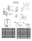


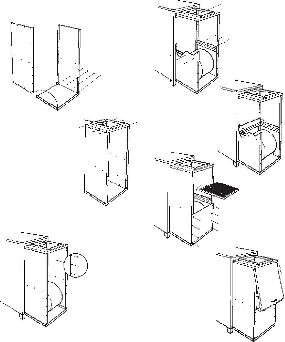
OF EITHER SIDE AT THIS POINT.
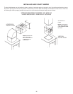
4. Attach filter holders to sides of enclosure with sheet metal
screws.
5. Position filter filler
between side filter
holders and secure
to back of furnace
with two self-tapping
screws.
6. Attach blower access
cover to enclosure with
sheet metal screws.
Insert filter (not supplied).
7. Attach handle to filter
cover and slide into
position.
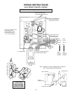
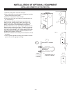
8. Connect cold air return
duct to top flange of
filter box.
NOTE: Drill, punch, or
cut access holes as
necessary for entrance
of power cables,
thermostat wire and
domestic hot water coil
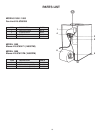
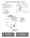
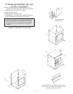
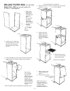
DELUXE FILTER BOX
Model 1600 / 1800 (see service bulletin #2)
16" x 20" x 1" Filter Required
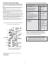
1. Attach sides
of filter box to
bottom with
(4) sheet metal
screws per
side.
Be sure sides
are inside
bottom lips
and positioned
with predrilled
holes as
illustrated.
Side with no
lip faces
back of
furnace.
2. Position top so 2" wide lip is
turned toward furnace. Place
top over sides and secure
with (4) sheet metal screws
per side.
3. Center assembly from left to right on back of furnace with
bottom of filter box resting on edge of furnace bottom.
Be sure filter
box is perfectly
square. Mark
position of screw
holes on back of
furnace. Drill
starter holes and
secure assembly
to back of furnace
with self-tapping
screws.
NOTE: DO NOT PLACE A SCREW IN THE MIDDLE HOLE
2" Lip
27
16" x 20" opening
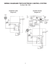
KIT #C61999