


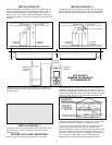
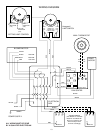
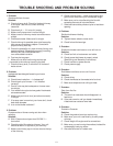
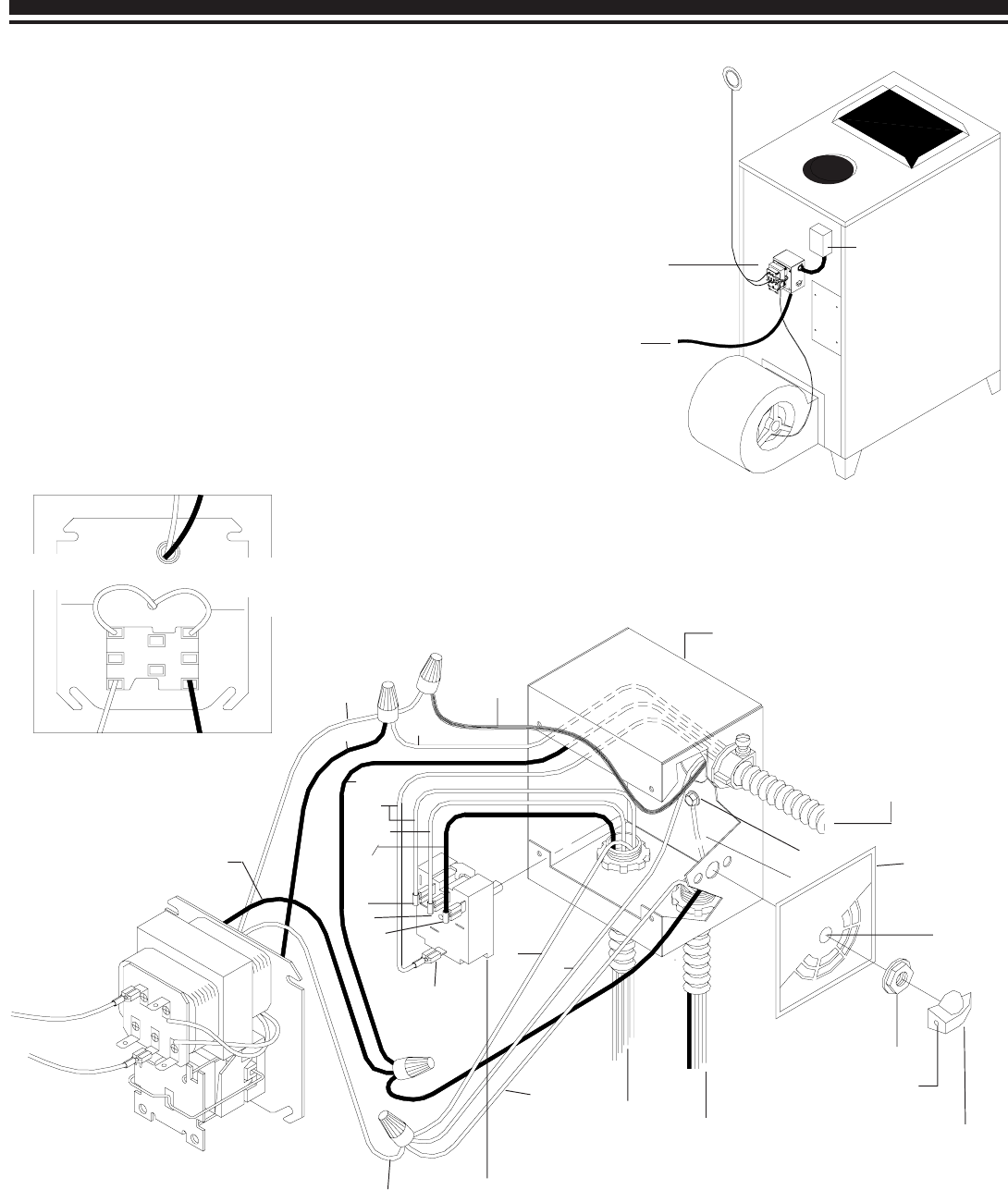
DRAFT WIRING DIAGRAM
ALL WIRING MUST
BE DONE BY A
QUALIFIED
ELECTRICIAN
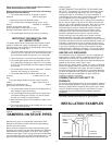
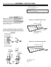
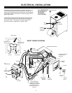
Predrilled holes are provided on the back of the furnace
for mounting the fan center electrical box. Mounting
holes and knockouts are also provided to accommodate
mounting the high limit control in either the upper left or
upper right corner.
The flexible conduit connecting the high limit control to
the fan center electrical box has been sized longer for
the model 1800. This conduit may be cut shorter to
provide a cleaner installation on model 1600.
9
FAN
CENTER
HIGH
LIMIT
CONTROL
THERMOSTAT
TO
THERMOSTAT
TO
"R"
TO
"G"
FAN
CENTER
W
W
W
W
L1
1
3
WIRES TO
BLOWER
MOTOR
PLASTIC
KNOB
SET
SCREW
NUT
PUNCH
GR
FLEXIBLE CONDUIT
TO HIGH LIMIT
CONTROL
BLK
BLUE
RED
BLK
BLK
BLUE
BLACK
TO DRAFT
RED
BLK
ELECTRICAL BOX
2
BLACK
BLUE
Wired to "G" on
fan center front
Wired to "G" on
fan center front
Red-
To Draft
Black-
To High Limit
GND
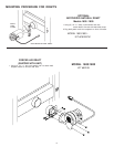
REAR VIEW
3-SPEED SWITCH
MODEL "B" SHOWN
(SEE WIRING DIAGRAM
ON PAGE 10 FOR
WIRING OF MODEL "A"
SWITCH)
HOUSE
CURRENT
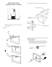
ELECTRICAL INSTALLATION
SWITCH
LABEL
CONDUIT
TO HOUSE
CURRENT