


10
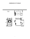
ASSEMBLY OF FURNACE
Your furnace requires the following items
to be assembled or installed by the service
person:
Feed Door Pull Handle
Feed Door Locking Handle
Blower(s) and Blower Controls
Electrical Connections
Remove all parts from inside the furnace
and inspect for damage, including the
firebrick as some breakage could occur
during shipment.
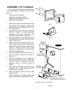
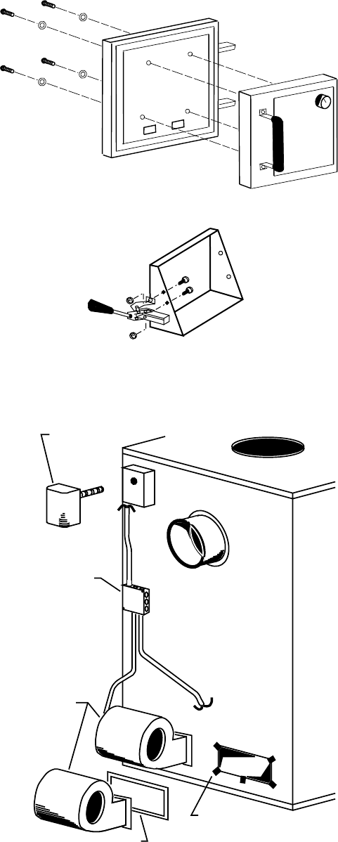
Assemble the feed door pull handle as
shown in Figure 8. Install thermostat
assembly and cover (complete with
handle) as illustrated in Figure 8.
Align thermostat control knob with flat on
thermostat control shaft and press onto
shaft. (See Fig. 8)
Attach feed door locking handle as in
Figure 9 with screws and nuts provided.
Note: Slotted holes are for adjustment of
handle. Adjust handle until some
pressure is required to lock feed door
during firing sequence.
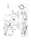
Install Honeywell Fan/Limit Control on
rear of furnace cabinet as shown in
Figure 10.
Remove blower(s) from carton(s).
Remove junction box cover. Attach clip
nuts as in Figure 10. Install blower(s) and
gasket(s) with 1/4"-20x3/4" bolts as
shown.
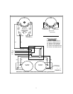
Wire right side blower first (See wiring
diagram, Fig. 11) and replace cover on
junction box on blower.
Wire left blower same as above and
replace cover.
Check operation of shaker grates with
grate handle before operating furnace.
1.
2.
3.
4.
5.
6.
7.
8.
Honeywell
FAN/LIMIT
CONTROL
4" ELECTRICAL
JUNCTION BOX
BLOWER
ASSEMBLY
GASKET
CLIP NUTS
(DO NOT USE CLIP NUT
ON UPPER CENTER HOLE)
Fig. 10
Fig. 9
Fig. 8
(MODEL 1537G- 2 BLOWERS)