


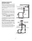
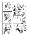
THERMODISC
THERMODISC
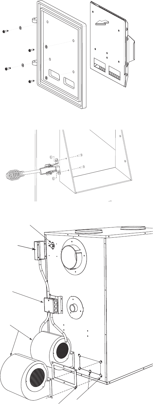
COVER
4” ELECTRICAL
JUNCTION BOX
BLOWERS
BLOWERS GASKET
CLIP NUTS
(Not used in the upper center hole.)
Assembly of Furnace
Your furnace requires the following items to be as-
sembled or installed by the service person:
Feed Door Pull Handle
Feed Door Locking Handle
Blowers and Blower Controls
Electrical Connections
1. Remove all parts from inside the furnace and in-
spect for damage, including the rebrick as some
breakage could occur during shipment.
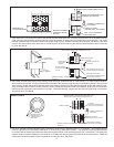
2. Assemble the Damper Box Assembly to the Feed
Door and the Black Knob to the Damper Box if not
already installed. Ensure the damper operates
by sliding the knob up and down. Damper should
operate freely with slight tension.
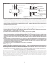
3. Attach feed door locking handle as in Figure 14
with screws and nuts provided. Note: Slotted holes
are for adjustment of handle. Adjust handle until
some pressure is required to lock feed door during
ring sequence.
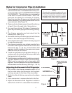
4. Install the thermodisc on rear of furnace cabinet
with the two screws provided. Mount the conduit
assembly from the junction box to the thermostat
bracket. Crimp the two female terminals to each
of the wire leads. Plug the wires to the thermodisc.
NOTE: It does not matter which of the two wires
plugs to which terminal on the thermodisc.
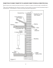
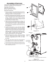
5. Remove blowers from cartons. Remove junction
box cover. Attach clip nuts as in Figure 15. Install
blower(s) and gasket(s) with 1/4"-20 x 3/4" bolts
as shown.
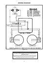
6. Wire right side blower rst (See wiring diagram)
and replace cover on junction box on blower.
7. Wire left blower same as above and replace cover.
8. Check operation of shaker grates with grate handle
before operating furnace.
Figure 15
(Model 1357M has only one blower)