NOTE: DIAGRAMS & ILLUSTRATIONS ARE NOT TO SCALE.
10
DETAILED INSTALLATION STEPS
TYPICAL INSTALLATION SEQUENCE
The typical sequence of installation follows,
however, each installation is unique resulting
in variations to those described.
See the Page numbers references in the follow-
ing steps for detailed procedures.
Step 1. (Page 10) Construct the appliance fram-
ing. Position the appliance within the framing and
secure with nailing fl anges.
Step 2. (Page 10) Route gas supply line to appli-
ance location.
Step 3. (Page 13) Install the vent system and
exterior termination.
Step 4.(Page 25) Field Wiring
a. Millivolt Appliances – Install the OFF/ON
burner control switch.
b. Electronic Appliances – Connect 120 VAC
electrical power to the appliance receptacle.
Step 5. (Page 26) Install blower kit (optional
equipment).
Step 6. ( Page 27) Make connection to gas
supply.
Step 7. (Page 28) Checkout appliance operation.
Step 8. (Page 28) Install embers, volcanic stone
and embers.
Step 9. (Page 29) Install glass enclosure pan-
els.
Step 10.(Page 29) Adjust burner primary air shutter
to achieve proper fl ame appearance.
Step 11 (Page 30) Install the decorative trim and
hoods.
Step 1. FRAMING
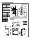
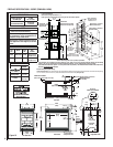
Frame these appliances as illustrated in Figures
13 & 14. All framing details must allow for a
minimum clearance to combustible framing
members as shown in Table 7 on Page 9.
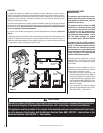
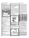
1. Remove the shipping carton.
2. Remove the top louvered panel and locate the
pressure relief plates.
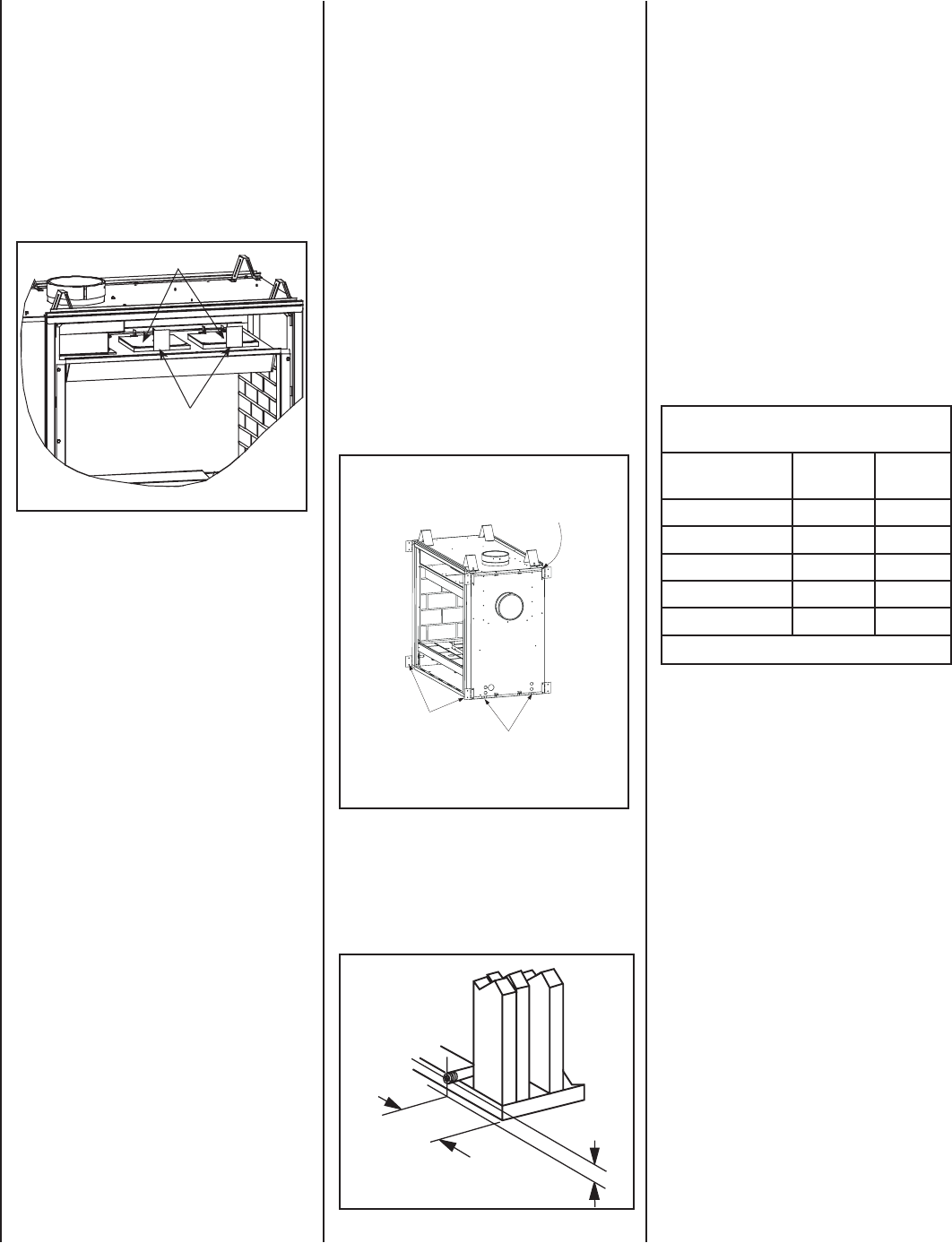
3. Lift the pressure relief plates and remove
the cardboard from beneath each plate (be
careful not to damage the white gasket). See
Figure 10.
* NOTE: INSTALLATION DIAGRAMS AND
INSTRUCTIONS SHOW THE FRONT OF
THE APPLIANCE AS THE SIDE WHICH HAS
VALVE ACCESS, EXCEPT WHERE NOTED.
Also see
Figures 13 & 14
5-5/8"
(143 mm)
3-1/8"
(79 mm)
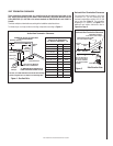
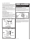
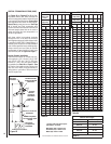
Figure 12 - ROUTE GAS LINE
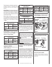
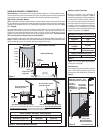
Proper Sizing of Gas Line
Properly size and route the gas supply line
from the supply regulator to the area where the
appliance is to be installed per requirements
outlined in the National Fuel Gas Code, NFPA
54 - latest edition (USA) or B149 - latest edition
(Canada). Never use galvanized or plastic pipe.
Refer to Table 8 for proper sizing of the gas
supply line, if black iron pipe is being used. Gas
lines must be routed, constructed and made
of materials that are in strict accordance with
local codes and regulations. We recommend
that a qualifi ed individual such as a plumber
or gas fi tter be hired to correctly size and route
the gas supply line to the appliance. Installing
a gas supply line from the fuel supply to the
appliance involves numerous considerations of
materials, protection, sizing, locations, controls,
pressure, sediment, and more. Certainly no one
unfamiliar and unqualifi ed should attempt sizing
or installing gas piping.
Schedule 40 / Black Iron Pipe
Inside Diameter (Inches)
Schedule 40 Pipe
Length (feet)
Natural
Gas
Propane
Gas
0-10 1/2 3/8
10-40 1/2 1/2
40-100 1/2 1/2
100-150 3/4 1/2
150-200 3/4 1/2
Table 8
Notes:
• All appliances are factory-equipped with a
fl exible gas line connector and 1/2 inch shutoff
valve (see Figure 47 on Page 27).
• See Massachusetts Requirements on Page
3 for additional requirements for installations
in the state of Massachusetts in the USA.
• The gas supply line should Not be connected
to the appliance until Step 6 (Page 27).
• A pipe joint compound rated for gas should be
used on the threaded joints. Ensure propane
resistant compounds are used in propane
applications. Be very careful that the pipe
compound does not get inside the pipe.
• It is recommended to install a sediment trap
in the supply line as close as possible to the
appliance (see Figure 47). Appliances using
Propane should have a sediment trap at the
base of the tank.
• Check with local building offi cial for local code
requirements (i.e. are below grade penetrations
of the gas line allowed?, etc).
IMPORTANT: If propane is used, be aware that
if tank size is too small (i.e. under 100-lbs, if
this is the only gas appliance in the dwelling.
Ref. NPFA 58), there may be loss of pressure,
resulting in insuffi cient fuel delivery (which
can result in sooting, severe delayed ignition
or other malfunctions). Any damage resulting
from an improper installation, such as this, is
not covered under the limited warranty.
Step 2. ROUTING GAS LINE
Route a gas line along the inside of the right side
framing as shown in Figure 12. Gas lines must
be routed, constructed and made of materials
that are in strict accordance with local codes
and regulations.
If the appliance is to be elevated above fl oor
level, a solid continuous platform must be
constructed. Headers may be in direct contact
with the appliance top spacers but must not be
supported by them or notched to fi t around them.
All construction above the appliance must be
self supporting, DO NOT USE THE APPLIANCE
FOR STRUCTURAL SUPPORT.
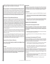
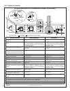
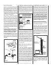
Side Nailing Flanges
The fi replace should be secured to the fram-
ing at the side(s) of the appliance using the
factory-provided nailing fl anges. Install the 8
nailing fl anges as shown in Figure 11 using the
existing screws. Position the fi replace within
the framing. When required, the tabs may be
bent 90 degrees by hand or with the assistance
of a hammer. Use wood screws to secure the
nailing fl anges to the framing. See Table 7 on
Page 9 for clearances of framing members
to cabinet parts. The nailing fl ange itself can
directly contact framing.
Floor Nailing Tabs - Secure the fi replace to the
fl oor as shown in Figure 11.
Figure 11 - Nailing Flanges
Remove these screws and use them
when installing nailing fl anges.
Nailing Flanges
Turn nailing tabs down and secure to fl oor with 8d
nails or other appropriate fasteners on both sides of
appliance which do not have viewing glass panels.
SSDVST Shown (SSDVPF - No nailing
fl anges on end with glass panel)
Figure 10
REMOVE
C
A
R
D
B
O
A
R
D
BEF
O
R
E U
S
IN
G
REMOVE
C
A
R
D
B
O
A
R
D
BEF
OR
E
US
IN
G
Pressure Relief Plates
Remove Cardboard Before
Using Appliance


