


VAV-SVN01E-EN 49
Wiring
Diagrams
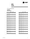
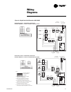
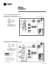
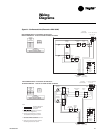
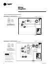
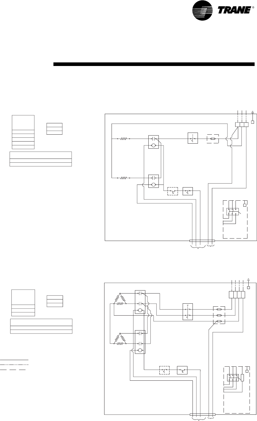
Figure 21 – Fan-Powered Units (Electronic or DDC/UCM)
1.
3. Load carrying P.E. Switches or Contactors
are supplied depending upon amp drawn.
Cutout are provided as standard.
4. Auto Reset Thermal Cutout and Manual Reset
5. Heater Line Fuses, Airflow Switch, and Door
FAN-POWERED UNITS - ELECTRONIC OR DDC/UCM -
HEATER TERMINALS - TYPICAL OF SINGLE PHASE VOLTAGES
HEATER TERMINALS - TYPICAL OF THREE PHASE VOLTAGES
FAN-POWERED UNITS - ELECTRONIC OR DDC/UCM -
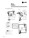
WHT
BLK
BRN
PUR
(See Nameplate)
Line Voltage
TB4
G
G
L1
L2
Disconnect
Switch
Door
Optional
Cutout
Manual Reset
Contactor
1st Stage
Switch
Optional
Air Flow
Thermal Cutout
Auto Reset
24V Input from
Controller
Output to Motor
115 or 277V
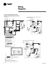
OR
BRN
WH
BK
PUR
Manual Reset
Cutout
Optional
Air Flow
Switch
Auto Reset
Thermal Cutout
Switch
Optional
Disconnect
Door
Output to Motor
115 or 277V
Controller
24V Input from
L1 L2 L3
G
L1 L2 L3
L2L1 L3
G
with each unit (2-stage shown).
2. Actual heater wiring diagrams are supplied
FIELD INSTALLED
OPTIONAL
FACTORY INSTALLED
Optional
Fuse
2nd Stage
Contactor
(See Nameplate)
Line Voltage
Fuse
Optional
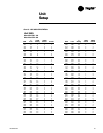
208
480
575
VOLTAGES
LINE
2
240
Mercury Contactors (MERC)
Magnetic Contactors (MAGN)
277
HEATER
CONTACTORS
STAGES
VOLTAGES
208
LINE
1
347
480
Mercury Contactors (MERC)
Magnetic Contactors (MAGN)
CONTACTORS
HEATER
STAGES
1
2
Notes:
THREE
PHASE
Interlocking Disconnect are optional.
2nd Stage
Contactor
1st Stage
Contactor
TB4
PHASE
SINGLE
L1 L2 L3 N - 208,480,600
L1 N - 277, 347
L1 L2 N - 208, 240, 480
L2L1
N
OR
N
L1 L2 N
N
N
N