


29TWA-PRC001-EN
Performance
Data
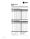
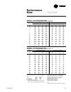
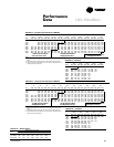
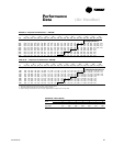
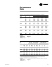
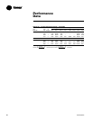
Table PD-23— Discharge Plenum And Grille Assembly Throw Distance — Air Handler
Unit Louver Angle Deflection Position
Model No. CFM L/S Straight 20, Ft. (m) 40, Ft. (m) 55, Ft. (m)
1400 661 38 (11.6) 24 (7.3) 22 (6.7) 18 (5.5)
1600 755 42 (12.8) 31 (9.4) 26 (7.9) 20 (6.1)
TWE050 1800 850 46 (14.0) 37 (11.3) 29 (8.8) 22 (6.7)
2000 944 48 (14.6) 43 (13.1) 33 (10.1) 24 (7.3)
2200 1038 51 (15.5) 50 (15.2) 36 (11.0) 25 (7.6)
2100 991 49 (14.9) 38 (11.6) 31 (9.4) 27 (8.2)
2400 1133 52 (15.9) 43 (13.1) 35 (10.7) 29 (8.8)
2700 1274 55 (16.8) 48 (14.6) 38 (11.6) 31 (9.4)
TWE075 3000 1416 58 (17.7) 53 (16.2) 42 (12.8) 32 (9.8)
3200 1510 56 (17.1) 46 (14.0) 38 (11.6) 30 (9.1)
3600 1699 62 (18.9) 51 (15.5) 42 (12.8) 33 (10.1)
4000 1888 66 (20.1) 57 (17.4) 47 (14.3) 35 (10.7)
4400 2077 71 (21.6) 62 (18.9) 52 (15.9) 38 (11.6)
TWE100 4800 2265 76 (23.2) 67 (20.4) 56 (17.1) 42 (12.8)
4300 2029 42 (12.8) 32 (9.8) 29 (8.8) 21 (6.4)
4900 2313 47 (14.3) 38 (11.6) 32 (9.8) 25 (7.6)
5400 2549 52 (15.9) 44 (13.4) 37 (11.3) 29 (8.8)
TWE155 6000 2832 57 (17.4) 49 (14.9) 41 (12.5) 32 (9.8)
5600 2643 50 (15.2) 40 (12.2) 33 (10.1) 27 (8.2)
6400 3020 56 (17.1) 46 (14.0) 38 (11.6) 30 (9.1)
7200 3398 62 (18.9) 51 (15.5) 42 (12.8) 33 (10.1)
TWE200 8000 3776 66 (20.1) 57 (17.4) 47 (14.3) 35 (10.7)
Throw distance values are based on a terminal velocity of 75 FPM (0.38 m/s).
Throw distance values at other terminal velocities may be established by multiplying throw distances in table above by
throw factor:
Terminal Velocity Throw Factor
50 FPM (.25 m/s) x 1.50
100 FPM (.51 m/s) x .75
150 FPM (.76 m/s) x .50
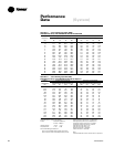
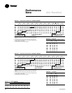
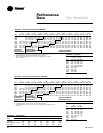
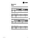
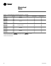
PD-24 — Static Pressure Drop Through Accessories — Air Handler
Discharge
Unit Return Grille Plenum and Grille
2
Electric Heaters (Kw)
Model No. CFM L/S In. W.C.
1
Pascal In. W.C.
1
Pascal 3.5-7 10-14 17-24 35
1400 661 .09 (22.4) .16 (39.8) .06 .06 .12 —
TWE050A 1600 755 .12 (29.9) .21 (52.3) 08 .08 .14 —
2000 944 .18 (44.8) .33 (82.2) .13 .13 .19 —
2100 991 .05 (12.5) .19 (47.3) .02 .03 .05 .08
TWE075A 2400 1133 .08 (19.9) .27 (67.2) .03 .06 .08 .12
3000 1416 .13 (32.4) .40 (99.6) .06 .12 .17 .23
TWE100A 2800 1321 .04 (10.0) .34 (84.7) .03 .04 .14 .20
TWE100B 3200 1510 .07 (17.4) .43 (107.1) .06 .13 .19 .26
4300 2029 .07 (17.4) .18 (44.8) .02 .02 .04 .05
4800 2265 .09 (22.4) .23 (57.3) .03 .03 .06 .08
TWE155B 6000 2832 .15 (37.4) .34 (84.7) .06 .06 .12 .17
5600 2643 .07 (17.4) .32 (79.7) .04 .04 .10 .15
TWE200B 6400 3020 .11 (27.4) .43 (107.1) .06 .0-6 .13 .19
8000 3776 .17 (42.3) .66 (164.3) .10 .10 .20 .30
1. Return air filter ESP included in Fan Performance Table data.
2. At louver opening angle of 42° F (5.5° C). For ESP at other angle openings, see accessory Installer’s Guide.
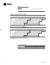
Throw distance values are based on a terminal velocity of 75 FPM (0.38 m/s).
Throw distance values at other terminal velocities may be established by multiplying throw distances in table above by
throw factor:
Terminal Velocity Throw Factor
50 FPM (.25 m/s) x 1.50
100 FPM (.51 m/s) x .75
150 FPM (.76 m/s) x .50
.