


TRG-TRC013-EN 17
period one
Fan Performance
notes
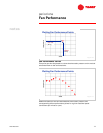
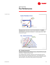
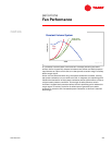
System Resistance Curve
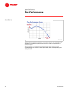
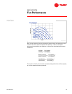
Now that a typical fan performance curve has been developed, let’s see how the
fan will perform within a system.
With each airflow, an air distribution system imposes a certain resistance to the
passage of air. The resistance is the sum of all of the pressure losses
experienced as air passes through the ductwork, supply air diffusers, return air
grilles, dampers, filters, coils, etc. This is the resistance, or static-pressure loss,
that the fan must overcome to move a given quantity of air through the system.
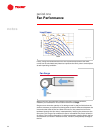
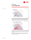
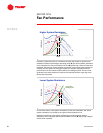
Assume that a system is designed to deliver 3,500 cfm [1.65 m
3
/s], and that to
overcome the system pressure losses, the fan must generate 2.0 in. H
2
O
[491 Pa] of static pressure.
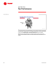
To illustrate how a system resistance curve is developed, this point is plotted on
the same chart used to develop the fan curve.
System Resistance
fan
fan
cooling
cooling
coil
coil
supply duct
supply duct
supply
supply
diffuser
diffuser
return air grille
return air grille
return duct
return duct
damper
damper
Figure 25
static pressure
static pressure
airflow
airflow
3,500 cfm
3,500 cfm
[1.65 m
[1.65 m
3
3
/s]
/s]
2.0 in. H
2.0 in. H
2
2
O
O
[491 Pa]
[491 Pa]
System Resistance
Figure 26