


10 TRG-TRC013-EN
notes
period one
Fan Performance
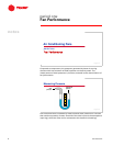
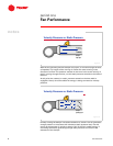
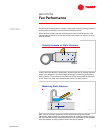
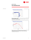
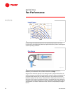
Next, the measured velocity pressure is used to calculate the airflow delivered
by the fan. The manometer measures the velocity pressure (P
v
) by subtracting
static pressure (P
s
) from total pressure (P
t
). Next, the air velocity (V) can be
calculated by dividing velocity pressure (P
v
) by the air density (ρ), taking the
square root of the quotient, and multiplying by a constant. Finally, the fan
airflow is determined by multiplying the air velocity (V) by the outlet area (A) of
the fan.
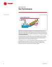
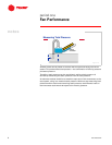
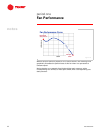
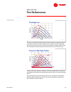
For example, assume the test readings for a specific throttling-device position
are as follows:
■ Total pressure (P
t
) = 2.45 in. H
2
O [62.2 mm H
2
O or 610 Pa]
■ Static pressure (P
s
) = 2.0 in. H
2
O [50.8 mm H
2
O or 491 Pa]
■ Velocity pressure (P
v
) = P
t
– P
s
= 2.45 – 2.0 = 0.45 in. H
2
O [11.4 mm H
2
O or 119
Pa]
■ Fan outlet area (A) = 1.28 ft
2
[0.12 m
2
]
■ Fan speed = 1,100 rpm (revolutions per minute)
■ Air density (ρ) at standard air conditions = 0.0749 lb/ft
3
[1.204 kg/m
3
]
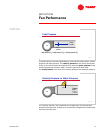
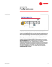
Proceeding with the calculations,
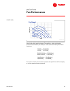
It is determined that at this point, the fan, operating at 1,100 rpm, is delivering
3,438 cfm [1.69 m
3
/s] against 2 in. H
2
O [491 Pa] of static pressure.
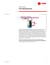
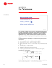
Determining Fan Airflow
Velocity Pressure (P
v
) = P
t
– P
s
Velocity (V) = Constant ×
Airflow = Velocity × Fan Outlet Area
√
P
v
ρ
Figure 15
V1,096
P
v
ρ
------ 1,096
0.45
0.0749
------------------ 2,686 fpm (ft/min)== =
Airflow V A× 2,686 1.28× 3,438 cfm (ft
3
/min)== =
V1.414
P
v
ρ
------ 1.414
119
1.204
--------------- 14.06 m/s== =
Airflow V A× 14.06 0.12× 1.69 m
3
/s== =