


2 TRG-TRC005-EN
notes
period one
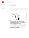
Refrigeration Cycle
First, a brief review of the vapor-compression refrigeration cycle will help to
relate these components.
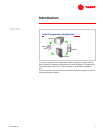
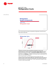
A diagram of a typical vapor-compression refrigeration cycle can be
superimposed on a pressure-enthalpy (P-h) chart to demonstrate the function
of each component in the system. The pressure-enthalpy chart plots the
properties of a refrigerant—refrigerant pressure (vertical axis) versus enthalpy
(horizontal axis). Enthalpy is a measure of the heat content, both sensible and
latent, per pound [kg] of refrigerant.
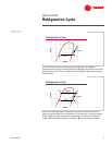
The cycle starts with a cool, low-pressure mixture of liquid and vapor
refrigerant entering the evaporator (A) where it absorbs heat from the relatively
warm air, water, or other fluid that is being cooled. This transfer of heat boils
the liquid refrigerant in the evaporator, and this superheated refrigerant vapor
is drawn to the compressor (B).
period one
Refrigeration Cycle
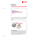
Refrigeration
System Components
Figure 3
A
B
pressure
pressure
enthalpy
enthalpy
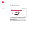
evaporator
evaporator
Refrigeration Cycle
Figure 4