


TCONT802AS32DA TOUCH SCREEN AND TCONT803AS32DA TOUCH SCREEN WITH DEHUMIDIFICATION
Pub. No. 18-HD25D19-3
69-1790—3 2
Do not install the comfort control where it can be affected
by:
— Drafts or dead spots behind doors and in corners.
— Hot or cold air from ducts.
— Radiant heat from sun or appliances.
— Concealed pipes and chimneys.
— Unheated (uncooled) areas such as an outside wall
behind the comfort control.
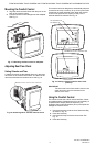
Installing Wallplate
CAUTION
Electrical Hazard.
Can cause electrical shock or equipment
damage.
Disconnect power before wiring.
The comfort control can be mounted horizontally on the
wall or on a 4 in. x 2 in. (101.6 mm x 50.8 mm) wiring box.
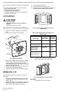
1. Position and level the wallplate (for appearance
only).
2. Use a pencil to mark the mounting holes.
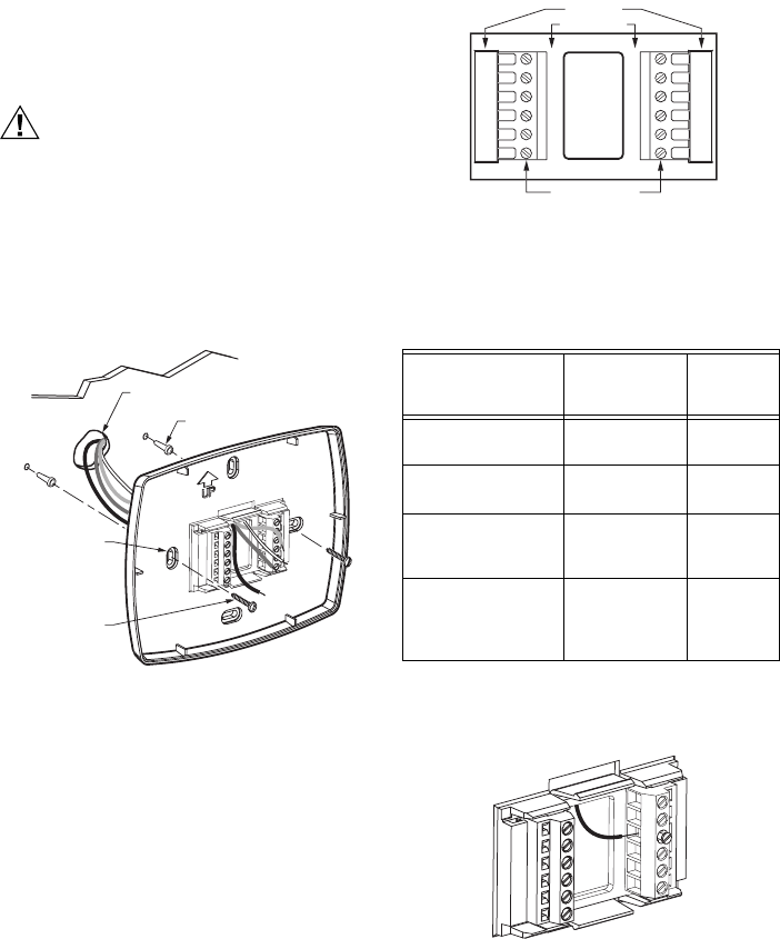
Fig. 2. Mounting wallplate.
3. Remove the wallplate from the wall and, if drywall,
drill two 3/16-in. holes in the wall, as marked. For
firmer material such as plaster, drill two 7/32-in.
holes. Gently tap anchors (provided) into the drilled
holes until flush with the wall.
4. Position the wallplate over the holes, pulling wires
through the wiring opening. See Fig. 2.
5. Insert mounting screws into the holes and tighten.
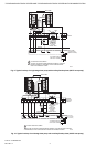
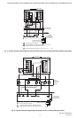
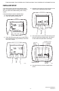
WIRING (FIG. 5-15)
All wiring must comply with local electrical codes and
ordinances.
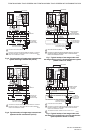
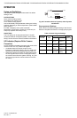
1. Select set of terminal identifications (Table 2) that
corresponds with system type (heat/cool or heat
pump in Fig. 3).
2. Loosen the screws for the appropriate system type
selected; see Table 2. Insert wires in the terminal
block under the loosened screw. See Fig. 4.
3. Securely tighten each screw.
4. Push excess wire back into the hole.
5. Plug the hole with nonflammable insulation to pre-
vent drafts from affecting the comfort control.
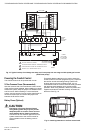
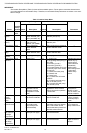
Fig. 3. Selecting terminal identifications for
system type.
NOTE: The factory default setting is configured for a
1 Heat/1 Cool System with a gas furnace.
Fig. 4. Inserting wires in terminal block.
IMPORTANT
Use 18 gauge comfort control wire.
WALL
MOUNTING
HOLES
M19916
MOUNTING
SCREWS (2)
WALL ANCHORS (2)
WIRES THROUGH WALL
AND WIRE SLOT
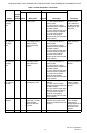
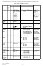
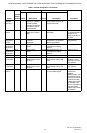
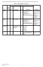
Table 2. Selecting Terminal Identifications for
System Type.
System Type
Wallplate
Terminal
Identifications
Wiring
Diagram
Reference
Standard Heat/Cool Heat/Cool Fig. 5,
Fig. 6
Standard Multistage
up to 2 Heat/2 Cool
Heat/Cool Fig. 7,
Fig. 8
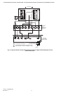
Heat Pump with
Electric Auxiliary
(Backup) Heat
Heat Pump Fig. 9,
Fig. 10,
Fig. 11
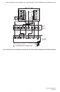
Heat Pump with
Fossil Fuel Auxiliary
(Dual Fuel) Heat
Heat Pump Fig. 12,
Fig. 13,
Fig. 14,
Fig. 15
HEAT
/COOL
SC
REW TERMINAL
S
HEAT P
U
M
P
M22636
Y2
F
X2
W1
S1
S2
Y2
W2
S1
S2
RC
R
O
Y
G
B
R
C
R
W1
Y
G
B
M19917