Pub. No. 22-1847-03 23
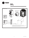
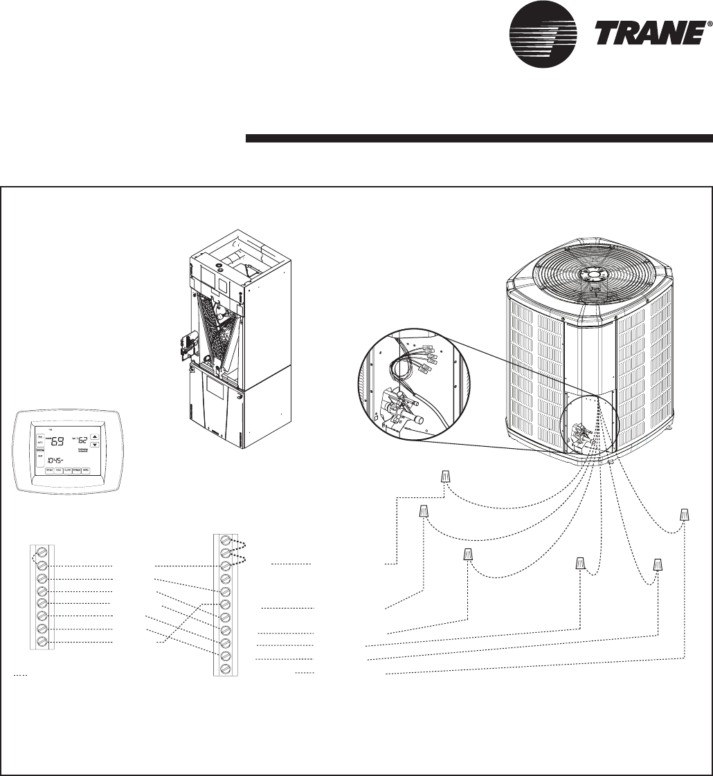
Comfort Control
Air Handler
Heat Pump
Neatly bundle all low voltage
wires behind the service
valve cover as shown.
Yellow/Red
Field wiring
Yellow
Blue
Black
(X2)
Red
Orange
Red
Yellow
Orange
Green
White
Blue
B
B - Blue
W
X2
G
Y1
Brown
Y2
Y1 - Yellow
Y2 - Brown
R
O
O
R
B
YI
W1
YO
Y2
BK
G
W2
W3 *
R - Red
O - Orange
(In)
(Out)
W1 - White
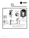
Two Stage HP
Field
Wiring
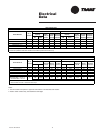
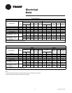
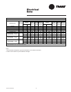
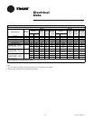
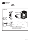
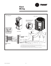
• * For multiple stages of electric heat, jumper W1, W2, and W3 together if comfort control has only one stage of heat
• YI and YO connections must be made as shown for freeze protection and internally mounted condensate overflow circuits to work properly
• Internally mounted condensate switch is optional and must be ordered separately
• If a 3rd party condensate overflow switch is installed, it should be wired in series between YO and Y to the outdoor unit


