


PKG-SVX14A-EN 9
Installation
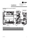
pre-installation
considerations
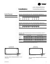
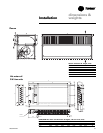
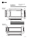
Table I-PC-1. Isolator load points, units with a vertical discharge configuration, lbs.
model L1 L2 L3 L4 L1 L2 L3 L4
SCRB/SIRB SCWB/SIWB
3-ton 99 105 120 127 105 133 118 124
5-ton 115 122 157 166 129 165 166 165
7.5-ton 154 203 227 221 177 234 230 231
10-ton 208 266 273 253 263 334 293 300
15-ton 243 332 359 356 315 388 382 375
Table I-PC-2. Isolator load points, units with a horizontal discharge configuration, lbs.
model L1 L2 L3 L4 L1 L2 L3 L4
SCRB/SIRB SCWB/SIWB
7.5-ton 250 108 313 135 285 126 319 140
10-ton 318 150 363 169 383 211 383 211
15-ton 404 166 510 210 514 215 514 215
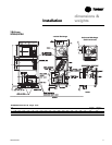
Table I-PC-3. Isolator load points & types, units with a horizontal discharge, inverted “L”
configuration, lbs.
air-cooled models water-cooled models
L1 L2 L3 L4 L1 L2 L3 L4
10-ton unit 318 150 363 169 383 211 383 211
spring red yellow red yellow red yellow red yellow
rubber-in-shear green red green red green red green red
15-ton unit 404 166 510 210 514 215 514 215
spring purple yellow purple yellow purple yellow purple yellow
rubber-in-shear gray red gray red gray red gray red
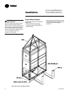
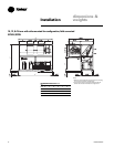
Note: Units ship with two different color isolators and should be placed as depicted in this chart to properly support the
unit weight. See Figures I-PC-1 & I-PC-2 for correct isolator positions by unit size.
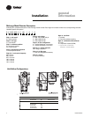
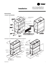
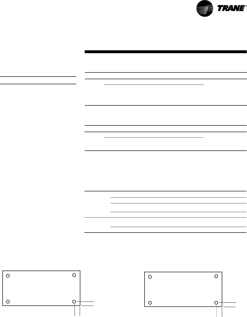
3, 5, & 7.5-ton units
bottom view of unit
1
7
/
8
1
7
/
8
7
/8” dia. hole under all 4 corners
Figure I-PC-1. Isolator mounting hole locations on 3, 5, &
7.5-ton units
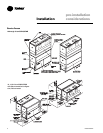
10 & 15-ton units
bottom view of unit
1
3
/
8
3
3
/
4
9
/16” dia. hole under all 4 corners
Figure I-PC-2. Isolator mounting hole locations on 10 & 15-
ton units
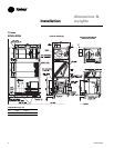
L1
L3
L2 L4
L1
L3
L2 L4
Isolator Placement
Note: Isolators are field-provided.