


R
Application
Considerations
WSHP-PRC003-EN
26
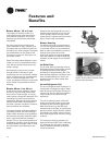
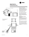
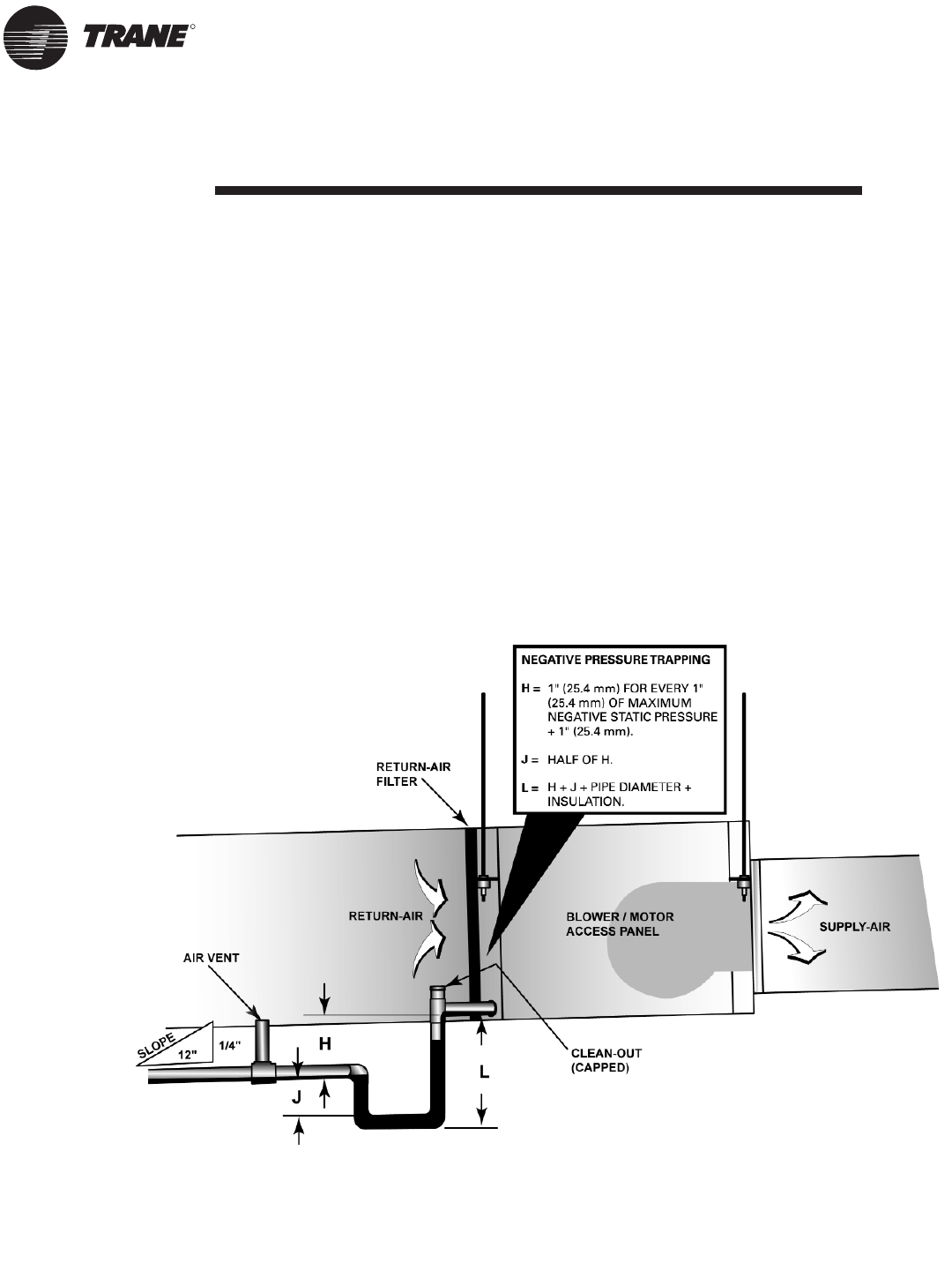
Condensate Traps
When designing a condensate trap for the
water-source system, it’s important to consider
the unit’s draw through design.
Under normal conditions, condensate runs
down the coil fins and drips into a condensate
pan. In situations where no trap is installed,
the water level that would be maintained in the
trap to create a seal, backflows through the
drainline into the unit. Because the fan pulls air
through the air-torefrigerant heat-exchanger,
this incoming air stream could launch water
droplets, forming at the base of the coil, into
the air.
Air flowing through the coil can then spray
condensate into the fan intake, with the possi-
bility of propelling moisture into other parts of
the mechanical system. This aerosol
mist can be carried through the ducts and into
the conditioned air space.
Another problem with air backflow, is the
source of that air. Drain lines typically flow into
waste or sewage lines, giving the potential to
introduce methane and other contaminants
from the drain system into the airstream.
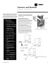
In a properly trapped system, when conden-
sate forms during normal operation, the water
level in the trap rises until there is a constant
outflow. (See Figure 31, for the appropriate
dimensions required in designing a negative
pressure system.)
Figure 31: Condensate trap installation.