


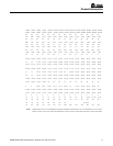

Unit Size 30 45 60 75 100 125 150 175 200 225 250 300 350 400
PERFORMANCE DATA ‡
Input BTU/Hr 30,000 45,000 60,000 75,000 100,000 125,000 150,000 175,000 200,000 225,000 250,000 300,000 350,000 400,000
Output BTU/Hr 24,000 36,000 48,000 60,000 80,000 100,000 120,000 140,000 160,000 180,000 200,000 240,000 280,000 320,000
Thermal Efficiency (%) 80 80 80 80 80 80 80 80 80 80 80 80 80 80
Free Air Delivery CFM 750 800 1,050 1,100 1,480 1,650 2,200 2,530 2,640 2,700 3,100 4,400 5,000 5,300
Air Temperature Rise
Deg. F
30 42 42 50 50 56 50 51 56 61 60 50 52 56
Outlet Velocity FPM 680 720 610 640 775 910 1,045 1,070 1,010 950 980 1,100 1,150 1,050
Full Load Amps at 115V 4.5 4.5 4.5 4.5 5.8 6 7.2 8.2 8.2 8.2 8.2 11.2 13.2 13.2
MOTOR DATA : Motor
HP
1/30 1/30 1/30 1/30 1/20 1/10 1/4 1/3 1/3 1/3 1/3 1/4 1/3 1/3
Motor Type SP SP SP SP SP SP PSC PSC PSC PSC PSC PSC PSC PSC
R.P.M. 1,050 1,050 1,050 1,050 1,050 1,050 1,140 1,140 1,140 1,140 1,140 1,140 1,140 1,140
Amps @ 115V 1.3 1.3 1.3 1.3 2.6 2.8 4 4.5 4.5 4.5 4.5 8 9 9
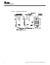
DIMENSIONAL DATA in.
“A” Height to Top of
Unit
25-3/4 25-3/4 25-3/4 25-3/4 31-1/4 31-1/4 36-1/4 36-1/4 36-1/4 36-1/4 36-1/4 36-1/4 36-1/4 36-1/4
“B” Width of Unit 14 14 17-1/2 17-1/2 17-7/8 20-5/8 20-5/8 23-3/8 26-1/8 28-7/8 31-5/8 37-1/8 42-5/8 48-1/8
“C” Height to Top of
Hanger
27-1/2 27-1/2 27-1/2 27-1/2 34-1/8 34-1/8 39-1/8 39-1/8 39-1/8 39-1/8 39-1/8 39-1/8 39-1/8 39-1/8
“D” Depth to Rear of
Housing
30-3/8 30-3/8 30-3/8 30-3/8 37-1/2 37-1/2 37-1/2 37-1/2 37-1/2 37-1/2 37-1/2 37-1/2 37-1/2 37-1/2
“E” Hanging Distance
Width
11 11 16-1/2 16-1/2 14-1/2 17-1/4 17-1/4 20 22-3/4 25-1/2 28-1/4 33-3/4 39-1/4 44-3/4
“F” Discharge Opening
Width
10 10 15-1/2 15-1/2 15-3/8 18-1/8 18-1/8 20-7/8 23-5/8 26-3/8 29-1/8 34-5/8 40-1/8 45-5/8
“G” Depth to Unit Side
Jacket
19-3/8 19-3/8 19-3/8 19-3/8 26-3/4 26-3/4 26-3/4 26-3/4 26-3/4 26-3/4 26-3/4 26-3/4 26-3/4 26-3/4
“H” Discharge Opening
Height
16-1/4 16-1/4 16-1/4 16-1/4 18 18 18 18 18 18 18 18 18 18
“J” to Centerline of
Flue
4 4 5-3/4 5-3/4 5-7/8 7-1/4 7-1/4 8-5/8 10 11-1/4 12-3/4 15-1/2 18-1/4 21
“K” Depth to Centerline
of Flue
23-5/8 23-5/8 23-5/8 23-5/8 30-5/8 30-5/8 30-5/8 30-5/8 30-5/8 30-5/8 30-5/8 30-5/8 30-5/8 30-5/8
“L” Hanger Location 13-3/4 13-3/4 13-1/2 13-1/2 16-1/4 16-3/4 16-3/8 16-3/8 16-3/8 16-3/4 16-3/4 16-3/4 16-3/4 16-3/4
Flue Size Dia.-in.* 4 4 4 4 4 4 4 4 5 5 5 6 6 6
Fan Diameter-in. 12 12 14 14 14 16 16 18 18 18 18 (2) 16 (2) 18 (2) 18
Gas Inlet-Natural Gas-
in.
1/2 1/2 1/2 1/2 1/2 1/2 1/2 1/2 1/2 3/4 3/4 3/4 3/4 3/4
Gas Inlet-LP Gas-in. 1/2 1/2 1/2 1/2 1/2 1/2 1/2 1/2 1/2 or 3/4
Approx. Shipping Wt
lb.
79 94 109 119 174 197 219 238 249 275 305 350 414 461
GHND-SVX01A-EN • High Efficiency Propeller Fan Gas Unit Heater 9
General Information
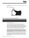
Note 1. ‡Ratings shown are for unit installations at elevations between 0 and 2,000 ft. For unit installations in U.S.A. above
2,000 ft. (610m), the unit input must be derated 4% for each 1,000 ft. (305m) above sea level; refer to local codes,