


GHND-SVX01A-EN • High Efficiency Propeller Fan Gas Unit Heater 21
Electrical Connections
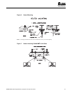
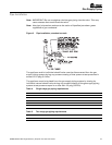
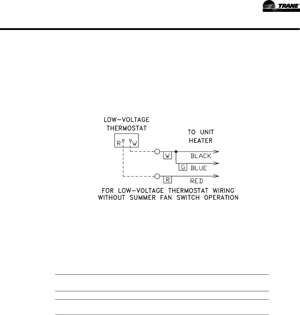
Thermostat wires tagged “W” and “G” must be connected together except when using
a general purpose "SPDT" 24VAC relay and a standard thermostat with subbase, or
when using low voltage thermostats. Also refer to Figure 9 for other wiring
connections.
THERMOSTAT HEAT ANTICIPATOR ADJUSTMENTS:
The initial heat anticipator setpoint should equal the thermostat's current amperage
draw when the unit is firing. This setpoint should be measured for the best results. Use
the recommended ranges as a guide. If further information is needed, consult your
thermostat manufacturer's instructions.
Recommended Heat Anticipator Setting Ranges:
FAN TIME DELAY CONTROL
Leads from time delay controls are factory wired to the junction box. The fan control is
a time delay relay (approximately 45 seconds ON, 65 seconds OFF). The fan control is
rated at 17 amps.
Note: The start-up fan delay must not exceed 90 seconds from a cold start.
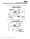
Note: For all wiring connections, refer to the wiring diagram that your unit is equipped
with (either affixed to the side jacket or enclosed in your unit's installation
instruction envelope). Should any original wire supplied with the heater have to
be replaced, it must be replaced with wiring material having a temperature
rating of at least 105° C.
Should any high limit switch wires have to be replaced, they must be replaced
with wiring material having a temperature rating of 200°C minimum.
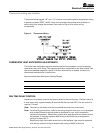
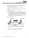
Figure 9. Thermostat Wiring
25 ft. (7.6m) 50 ft. (15.2m)
Gas Ignition Type T'stat Wiring T'stat Wiring
For Power Vented Units: 0.85 to 0.90 A 0.90 to 1.1 A
Intermittent (Spark) Max. Setting on thermostat
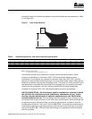
Thermostat wiring and location