


WSHP-SVX02A-EN 17
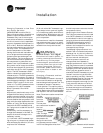
Controls Using 24 VAC
Before installing any wire, refer to the
electrical access locations on the unit
submittals located on pages 7 through
9.
Ensure that the AC control wiring be-
tween the controls and the unit’s ter-
mination point does not exceed three
(3) ohms/conductor for the length of
the run.
Note: Resistance in excess of 3-ohms
per conductor may cause component
failure due to insufficient AC voltage
supply.
Check all loads and conductors for
grounds, shorts, and mis-wiring.
Use copper conductors unless other-
wise specified.
Do not run the AC low voltage wiring
in the same conduit with the high volt-
age power wiring.
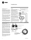
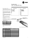
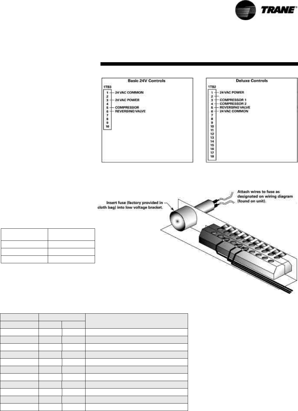
Low voltage connection diagrams are
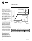
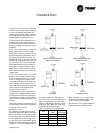
shown in Figure 9. Optional desuper-
heater fuse installation shown in Fig-
ure 10.
Table 4: 24V AC conductors
Distance
from unit to Control
Recommended
Wire Size
000-460 feet 18 gauge
461-732 feet 16 gauge
733-1000 feet 14 gauge
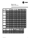
Table 5: Deluxe controller diagnostic LEDs
Color: Green Color: Red
Controller Mode
LED1 LED2 LED3
OFF OFF OFF Control OFF
ON OFF OFF Normal/Compressor OFF
ON OFF FLASH Anti-short Cycle
ON OFF ON Normal/Compressor ON
FLASH ON OFF Brownout Condition
ON FLASH ON Soft Lockout (low pressure)
ON FLASH FLASH Soft Lockout (high pressure)
ON ON ON Manual Lockout (low pressure)
ON ON FLASH Manual Lockout (high pressure)
ON FLASH OFF Manual Lockout (condensate overflow)
ON ON OFF Compressor Disable
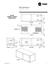
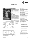
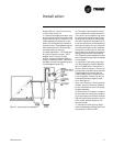
Installation
Low Voltage Wiring
Figure 9: Low voltage connection
Figure 10: Desuperheater fuse installation