


WSHP-SVX02A-EN 11
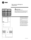
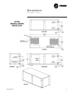
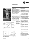
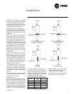
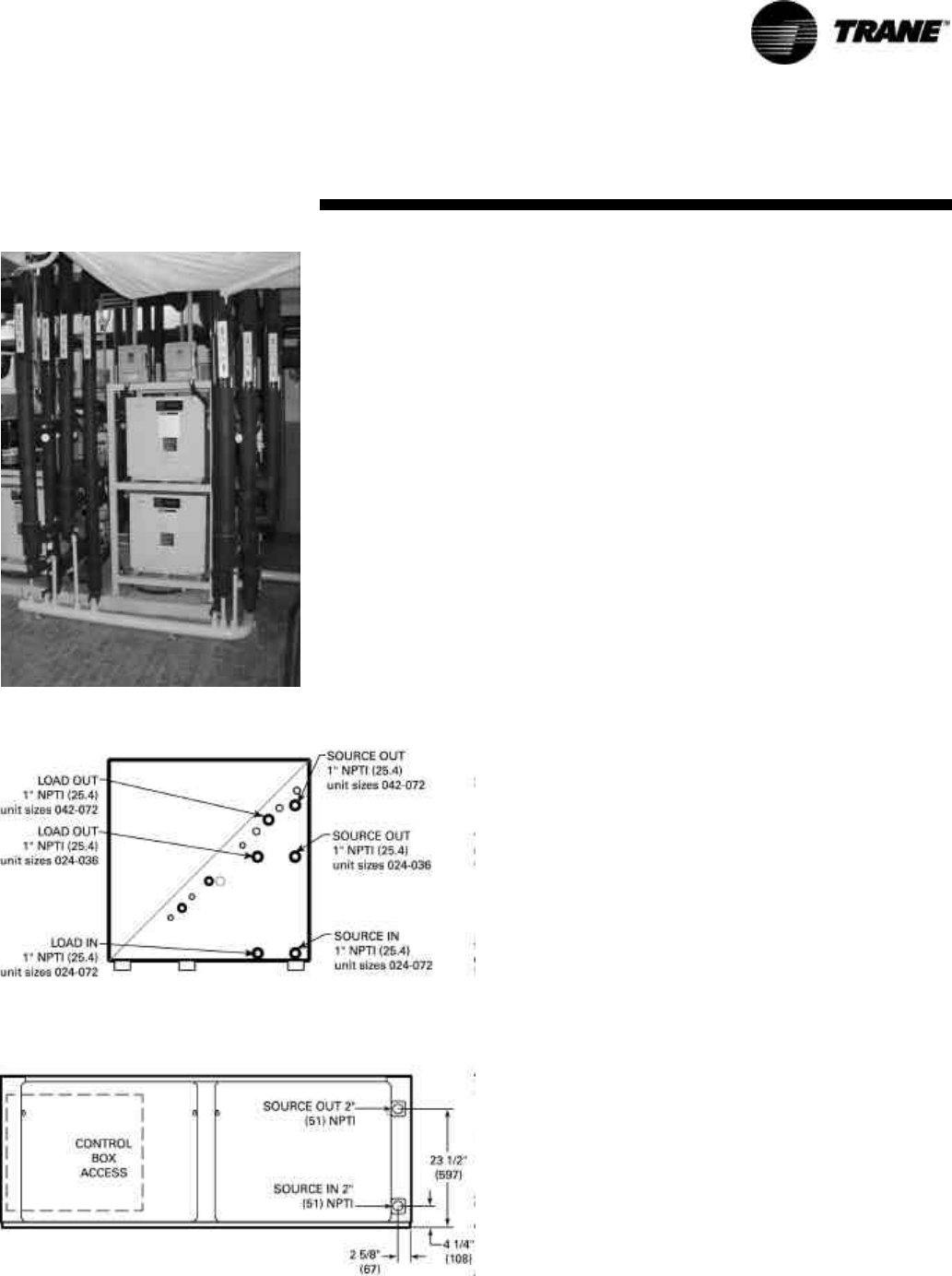
Figure 2: Racking installation
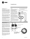
WARNING
Improper Unit Lift!
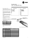
Test lift unit approximately 24
inches to verify proper center of
gravity lift point. To avoid
dropping of unit, reposition lifting
point if unit is not level. Failure to
properly lift unit could result in
death or serious injury or possible
equipment or property-only
damage.
Unit Placement
Units may be placed into a field sup-
plied mechanical rack (See Figure 2),
or placed on a finished floor. Loosen
compressor bolts to release tension of
the rubber grommets to help reduce
vibration during operation. Sound
proofing material (field supplied) is
recommended to help attenuate noise
generated by compressor vibration.
It is important to leave appropriate
clearances around the unit to achieve
maintenance and
serviceability to
the equipment.
See page 6 for
service clearance
dimensions.
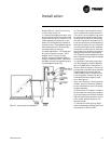
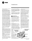
Water Connection
Connect the source-side and load-side
water-in/water-out from the water-to-
water heat pump to the source system
and the load system.
Note: The source for a water-to-water
heat pump is typically a boiler/cooling
tower or geothermal loop.
The load for a water-to-water heat
pump is typically fresh-air unit(s), fan
coil(s), hydronic coil(s), radiant heat,
wall fin, or potable water.
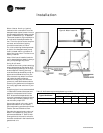
The source and load connections for
the 2-ton through 6-ton equipment is
on the right hand side of the unit.
The 20-ton equipment incorporates
the source-side connection at the
unit’s front, and the load-side connec-
tion at the unit’s back.
For vibration isolation, it is recom-
mended that flexible steel braided
hoses be installed instead of hard pip-
ing the equipment to the main loop
system or mechanical device.
Trane offers 4-types of hose kit varia-
tions:
• Stainless steel braided flexible
hose with manual shut-off (ball)
valves
• Stainless steel braided flexible
hose with manual deluxe shut-off
(ball) valves
• Stainless steel braided flexible
hose with manual circuit-setter
valve
• Stainless steel braided flexible
hose with automatic balancing
valve
Additional accessories, such as a
strainer are recommended for use to
eliminate contaminants from entering
the brazed-plate or co-axial water-to-
refrigerant heat exchangers.
Installation
Figure 3: Water connection