


16
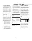
GSSD Units Coupled with
TWE Air Handlers
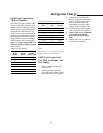
The GSSD IS coupled with the TWE-
E series. Table 4 may be used to deter-
mine the amount of charge necessary
for the split unit system without any
refrigerant line connecting the two.
Table 5 can be used to determine the
amount of refrigerant needed for lines.
By adding the two weights together,
the approximate total system charge
can be obtained. For fine tuning the
charge, see Units Coupled with Non-
TWE Air Handlers and Fine Tuning
in next section.
Note:
If piping runs exceed 50 feet, the next
highest pipe size should be used.
GSSD Units Coupled with
Non-TWE Air Handlers and
Fine Tuning
1. Place the GSSD system in the
cooling mode.
2. Throttle down the water flow
with a ball valve until the leaving
fluid temperature is 95 degrees F.
3. Charge the system unit until a
level of 10 degrees superheat is
achieved. To determine super-
heat, an accurate suction line
temperature needs to be taken
along with the suction pressure.
4. The sub-cooling will be approxi-
mately 8 degrees to 5 degrees F.
5. Allow system to run 20 minutes
for conditions to stabilize
before measuring the super-
heat.
6. Return water flow to 3 gpm per
nominal ton of capacity.
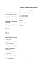
Table 4: R22 Requirements
GSSD
Model
Number
TWE
Model
Number
Lbs of R22
for both
GSSD & TWE
GSSD024 TWE031E 5.0
GSSD030 TWE031E 5.0
GSSD036 TWE040E 8.25
GSSD042 TWE040E 9.25
GSSD048 TWE065E 9.25
GSSD060 TWE065E 10.125
GSSD072 TWE065E 10.75‘
Table 5: R22 requirement per foot of line
O.D. Tube
Size
Liquid Line
(oz.)
Suction
Line (oz.)
1/4-inch 0.352 N/A
3/8-inch 0.928 N/A
1/2-inch 1.152 0.032
5/8-inch 1.840 0.048
3/4-inch 4.272 0.064
7/8-inch N/A 0.080
1 1/8-inch N/A 0.144
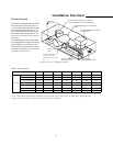
Refrigerant Charge