


ACDS-PRC001-EN6
Selection
Procedures
c
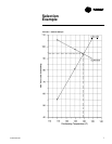
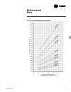
Transfer the results from the compressor
and condenser plots to Chart SP-1 and do
the following. Draw a line through the
two points representing gross heat
compressor capacities less subcooling
(105.6 and 82.3). Draw a line through the
two points representing condenser gross
heat of rejection (55.4 and 82.3).
d
At the point of intersection of the
compressor and condenser lines draw
dashed lines to the left and bottom
margins of Chart SP-1. The end points of
these lines will show a resultant gross
condenser capacity of 93.8 tons at 129.4 F
condensing temperature.
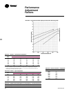
e
From chart PD-2 calculate the percent
increase in capacity due to subcooling.
When selecting a combination of
equipment, it becomes necessary to
match the compressor and condenser
performance. The following procedure
should be used in determining the
correct condenser.
First:
Determine the total cooling load and the
evaporator sst and compressor required.
Example:
Given – Total cooling load = 96 tons
– Ambient temp = 95 F
– Evaporator sst = 45 F
– Compressor – CUAB-D10E
The compressor was selected from
COM-DS-1 catalog according to the sst
and maximum acceptable condensing
temperature for adequate compressor
capacity.
a
Plot at least two gross compressor
capacities (less subcooling) at the design
suction temperature and different
condensing temperatures. (subcooling
factor is .047% per deg. F subcooling, 16
F for CUAB-D10E)
Example:
(From COM-DS-1)
CUAB-D10E Compressor at 45 F sst.
With:
115 F condensing temperature = 113.5
tons divided by 1.075 subcooling factor =
105.6 tons.
With:
125 F condensing temperature = 105.1
tons divided by 1.075 subcooling factor =
97.8 tons
b
Plot two gross condenser heat rejection
points on chart PD-1 divided by the
compressor N factor (Table PD-1 to PD-3)
at different condensing temperatures.
Example: Anticipating 100 ton
condenser to meet design load of 96
tons.
Gross Heat
Cond.
of Rejection
Temp ITD (MBh) = Tons ÷ N Factor = Tons
115 at 20 = 830 = 69.2 ÷ 1.25* = 55.4
125 at 30 = 1285 = 107.1 ÷ 1.30* = 82.3
*N factor corrected from Table PD-2
sst – saturated suction temperature
F – degree Fahrenheit
N – compressor factor
ITD – initial temperature difference
Example:
At 95 F ambient and 129.4 F condensing
temperature there is a 10.1% increase in
capacity due to subcooling. This yields a
system net capacity of 93.8 tons x 110%
= 103.2 tons.
f
If necessary use the values in Table PD-4
to adjust the system capacity for altitude.
g
Compare this result with the design
capacity and condensing temperature.
The required cooling load is 96 tons,
therefore, the CAUC-D10 is the proper
selection.
Repeat the process steps B through G as
necessary to achieve the most economic
condenser selection.