


18-HD64D1-1 7
CAUTION: EQUIPMENT DAMAGE HAZARD - Improper wiring can lead
to equipment damage. Follow the terminal connection information care-
fully to ensure the control is wired properly. After wires are secure, bare
wires MUST NOT touch each other. See the Field Wiring Diagrams for
specific system applications.
▲
CAUTION
!
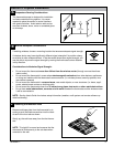
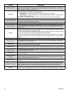
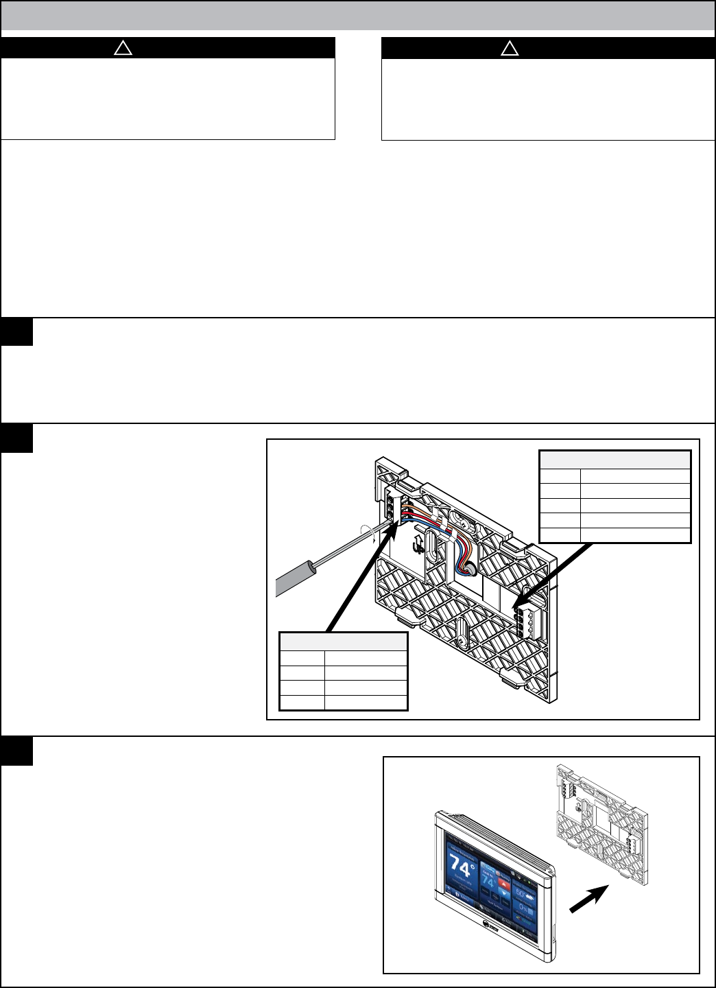
Connect wiring to terminals as
shown.
Route wiring within the plastic
channel as shown so that it does
not interfere with thermostat when
reinstalling. Do not overlap wires.
Plug the opening with non-flamma-
ble insulation to prevent drafts from
affecting the thermostat.
▲
WARNING
!
LIVE ELECTRICAL COMPONENTS!
During installation, testing, servicing, and troubleshooting of this prod-
uct, it may be necessary to work with live electrical components. Failure
to follow all electrical safety precautions when exposed to live electrical
components could result in death or serious injury.
D
R
B
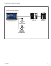
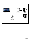
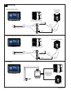
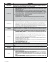
NOTE: The maximum total cable length for the entire communicating system is 500 feet 18 AWG. The maximum distance of any single
cable from a transformer is 250 feet 18 AWG.
NOTE:
Use 18-gauge color-coded thermostat cable for proper wiring. Shielded cable is not typically required. •
Keep this wiring at least one foot away from large inductive loads such as Electronic Air Cleaners, motors, line starters, lighting bal-•
lasts and large distribution panels.
Failure to follow these wiring practices may introduce electrical interference (noise) which can cause erratic system operation. •
All unused thermostat wire to be grounded at indoor unit chassis ground only. Shielded cable may be required if the above wiring •
guidelines cannot be met. Ground only one end of the shield to the system chassis.
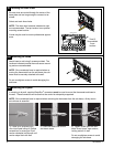
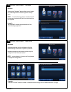
Replace unit flat onto sub-base being careful to
align unit correctly with the sub-base before apply-
ing force.
Thermostat should fit snug and not “rock” when
properly installed. Check wire routing if sub-base is
unstable.
Connect Wiring
Replace Thermostat
6
7
Section 4. Wiring
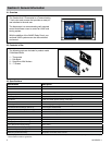
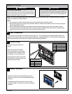
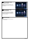
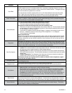
Optional Connections
Terminal Description
RS Remote Sensor
RS Remote Sensor
ODT Outdoor Temperature Sensor
ODT Outdoor Temperature Sensor
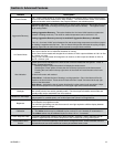
The thermostat is powered via 24 VAC from the indoor unit. On every application, 24VAC loads should be re-
viewed to be sure the indoor unit control power transformer is adequately sized. The ComfortLink II thermostat
draws approximately 4VA more than the typical communicating thermostat.
Power Connections
5
Thermostat Connections
Terminal Description
D Data
R
24 VAC (hot)
B 24 VAC (common)