ClimaDry Whole House Dehumidication - ClimateMaster Geothermal Heat Pumps - Rev.: 18 April, 2008B
13
Units equipped with ClimaDry must be ushed/purged
with a ush cart. Detailed general ushing /purging
instruction can be found in the Flow Controller III IOM.
The unit must be powered (but not operating) during
ushing/purging. Unit power is required to operate
the three-way modulating valve during ushing.
When ushing/purging units equipped with ClimaDry
the earth loop should be fully ushed/purged before
attempting to ush/purge the heat pump. Once the
earth loop is ushed, position the ushing valves to
ush the heat pump. Then with ushing ow re-directed
through the unit, energize the modulating three-way
dehumidication valve to allow ow through the
dehumidication hydronic circuit.
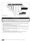
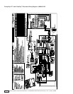
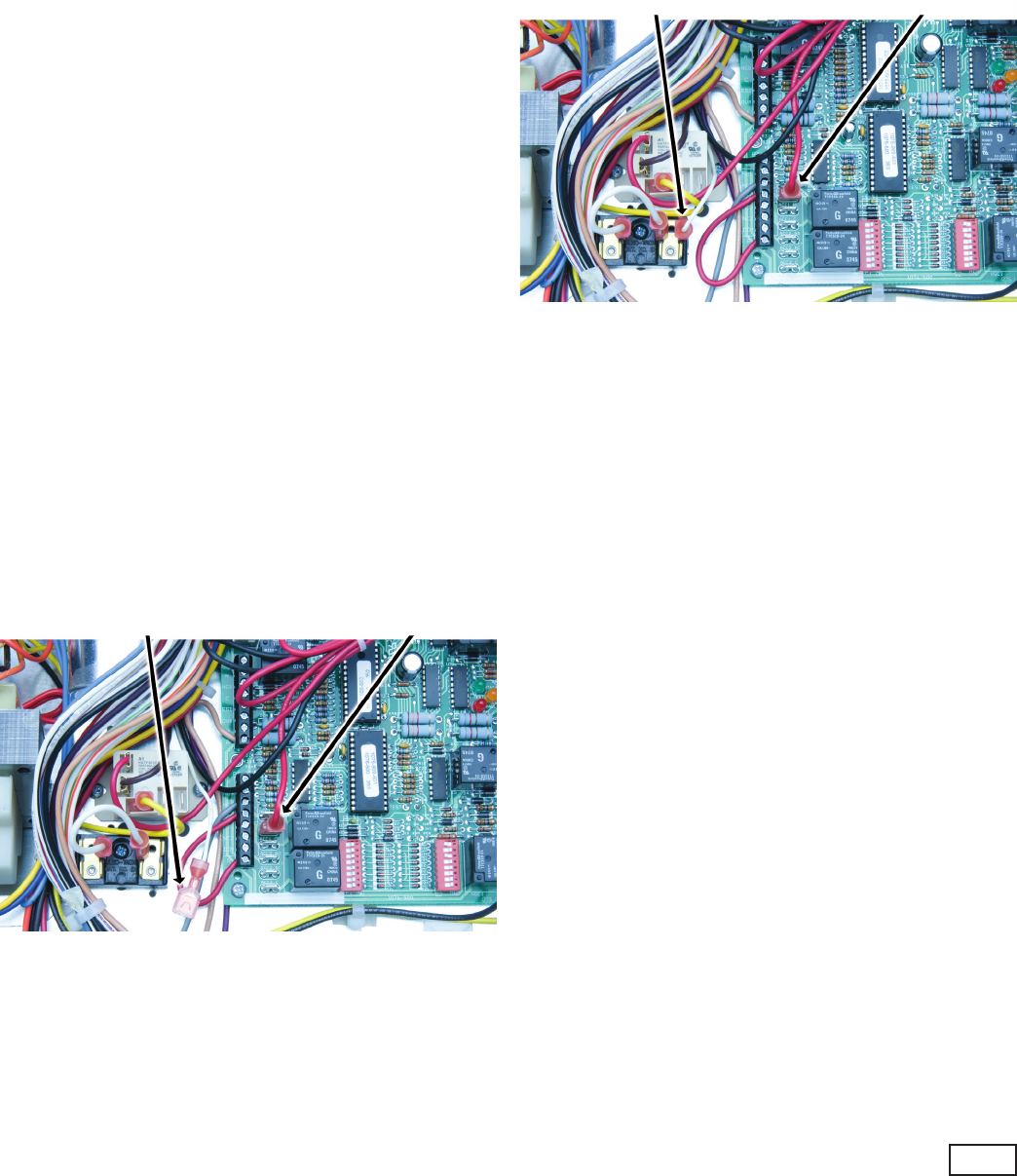
Energize the modulating three-way dehumidication
valve by removing the red wire from the ACC1 ‘N.O.’
terminal on the DXM board. Connect this wire to the
ACC1 ‘NC’ terminal of the DXM controller, as shown
in gure 1, to energize the modulating three-way
dehumidication valve. Once energized, the valve will
take 45 – 75 seconds to fully shift. Continue ushing
during this time. After the valve has completed its shift,
use the air bleed from the top of the reheat coil to purge
air from the coil.
Note, if the ClimaDry sensor, located in the supply
air stream is above 70°F it must be disabled to allow
the modulating valve to shift. Disable this sensor by
removing the white wire from the Low Voltage Terminal
Block (LVTB) shown in gure 1.
Figure 1. Flushing/Purging Wiring
De-energize the valve by removing the red wire from the
ACC1 ‘NC’ terminal on the DXM board. The valve will
spring return to its normal position in just a few seconds.
After the valve has fully returned, repeat the process of
running the valve through its cycle and purging air from
the reheat coil.
Flushing/Purging Units with ClimaDry
Under extreme circumstances this procedure may be
required multiple times to purge all air from the circuit.
After completing the ushing/purging procedure, restore
the red wire to the ACC1 ‘N.O.’ terminal on the DXM for
normal operation. Return the white sensor wire to the
LVTB, if it was removed, as shown in gure 2.
Figure 2. Normal Unit Wiring
Extra care must be taken when using non-pressurized
ow centers to ensure all air is removed from the unit
and no additional air is allowed into the system. If air is
allowed to collect in the ClimaDry piping, nuisance trips
may occur. Additional ush/purge cycles may be used
when required.
White Thermistor Wire Red Three-Way Valve Wire
White Thermistor Wire Red Three-Way Valve Wire


