


– 101 –
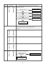
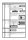
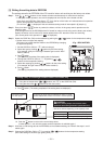
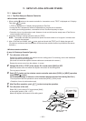
[3] Writing the setting data to EEPROM
The settings stored in the EEPROM of the P.C. board for indoor unit servicing are the factory-set values.
Step 1 Push
SET
,
CL
and
TEST
buttons on the remote controller simultaneously for more than 4 seconds.
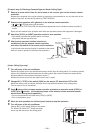
* In the group control operation, the unit No. displayed for the first time is the header unit No.
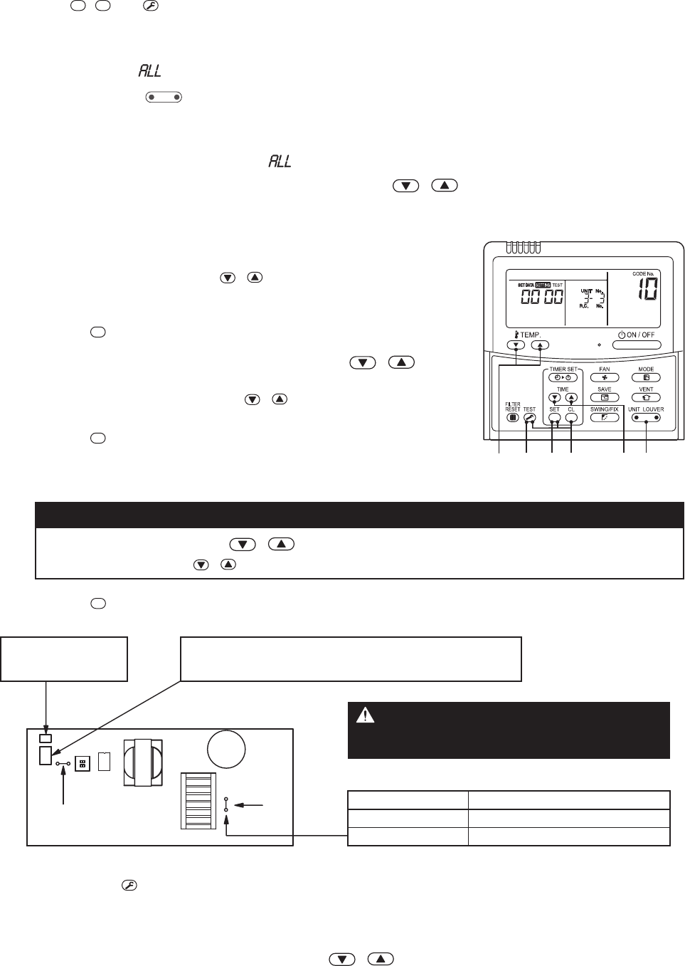
At this time, the CODE No. (DN) shows “
”. Also, the fan of the indoor unit selected starts its operation
and the swing operation starts if it has the louvers.
(The unit No. “
” is displayed if the auto-address setting mode is interrupted in [2] step 2 a))
Step 2 Every time when
UNIT LOUVER
button is pushed, the indoor unit Nos. in the group control operation are dis-
played in order.
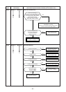
(The settings stored in the EEPROM of the P.C. board for indoor unit servicing are the factory-set values.)
Specify the indoor unit No. with its P.C. board replaced to the P.C. board for indoor unit servicing.
(You cannot perform this operation if “
” is displayed.)
Step 3 Select the CODE No. (DN) can be selected by pushing the
/ button for the temperature setting.
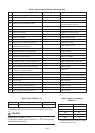
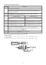
• Set the indoor unit type and capacity.
The factory-set values shall be written to the EEPROM by changing
the type and capacity.
1. Set the CODE No. (DN) to “
”. (without change)
2. Select the type by pushing
/ buttons for the timer setting.
(For example, 4-way Air Discharge Cassette Type is set to “0001”.
Refer to table 2)
3. Push
SET
button.
(The operation completes if the setting data is displayed.)
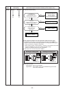
4. Change the CODE No. (DN) to “
” by pushing /
buttons for the temperature setting.
5. Select the capacity by pushing
/ buttons for the timer setting.
(For example, 80 Type is set to “0012”. Refer to table 2)
6. Push
SET
button.
(The setting completes if the setting data are displayed.)
9. Push
SET
button. (The setting completes if the setting data are displayed.)
10. Push the
TEST
button to return to the normal stop status.
(It takes approx. 1 min until the remote controller operation is available again.)
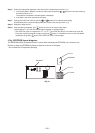
Step 4 Write the on-site setting data to the EEPROM, such as address setting, etc. Perform the steps 1 and 2
above again.
Step 5 Change the CODE No. (DN) to “
” by pushing / buttons for the temperature setting.
(this is the setting for the filter sign lighting time.)
Setting 4-way air discharge cassette Indoor Unit model only
7. Using the set temperature / buttons, set “+-” to the CODE No. (DN).
8. Using the timer time
/ buttons, set the data. (0001)
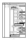
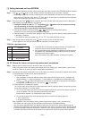
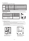
3651 42
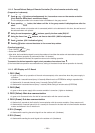
Connector (CN504)
for drain pump
CAUTION
Be sure to set the jumper wire since the motor
protection level setting selection is performed on it.
SW501
CN34
(Red)
J01
J02
Jumper wire (J02)
None
Required (factory setting)
SM56, 80 type
SM110, 140 type
* Set J02 as follows depending on the capacity class.
If the plug for short-circuit is attached on the P.C. board
before replacement, attach it on the P.C. board replaced.
<Fig. 1 RBC-AMT32E>