


– 112 –
EN-22 22
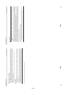
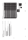
Super Digital Inverter
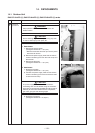
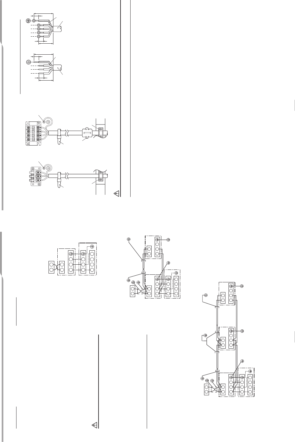
How to wire
1. Connect the connecting wire to the terminal as identified
with their respective numbers on the terminal block of the
indoor and outdoor units.
H07 RN-F or 60245 IEC 66 (1.5 mm
2
or more)
2. When connecting the connecting wire to the outdoor unit
terminal, prevent water from coming into the outdoor unit.
3.Insulate the unsheathed cords (conductors) with
electrical insulation tape. Process them so that they do
not touch any electrical or metal parts.
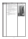
4. For interconnecting wires, do not use a wire joined to
another on the way.
Use wires long enough to cover the entire length.
5. Wiring connections differ in conformance
to EMC
standards, depending whether the system is single,
twin or triple. Connect wires according to respective
instructions.
CAUTION
•An installation fuse must be used for the power supply
line of this air conditioner.
• Incorrect/incomplete wiring may lead to an electrical fire
or smoke.
• Prepare an exclusive power supply for the
air conditioner.
• This product can be connected to the mains power.
Fixed wire connections:
A switch that disconnects all poles and has a contact
separation of at least 3mm must be incorporated in the
fixed wiri
ng.
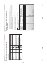
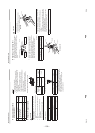
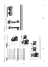
Wiring diagram
* For details on the remote controller wiring/installation,
refer to the Installation Manual enclosed with the remote
controller.
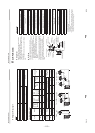
Single system
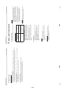
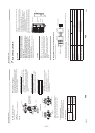
Simultaneous twin system
Simultaneous triple system (SP160
only)
*Use 2-core shield wire (MVVS 0.5 to 2.0 mm² or more) for the remote controller wiring in the simultaneous twin and
simultaneous triple systems to prevent noise problems. Be sure to
connect both ends of the shield wire to earth leads.
* Connect earth wires for each indoor unit in the simultaneous twin and simultaneous triple systems.
A B
1
1
L1
2
2
3
3
N
L2 L3
Remote controller
Remote controller wiring
Indoor side
Indoor/Outdoor connecting
wires
Outdoor side
Power supply
A B
1 2 3
A B
1
1
2
2
3
3
L1 L2 L3
N
Remote controller
Remote controller
wiring
Indoor side
Indoor/Outdoor
connecting wires
Outdoor side
Power supply
Indoor
side
Remote controller
inter-unit wiring
Indoor power
inter-unit
wiring
A B
1 2 3
A B
1
1
2
2
3
3
A B
1 2 3
L1 L2 L3
N
Remote controller
Remote controller
wiring
Indoor side
Indoor/Outdoor
connecting wires
Outdoor side
Power supply
Remote controller
inter-unit wiring
Indoor power
inter-unit wiring
Remote controller
inter-unit wiring
Indoor power
inter-unit wiring
Indoor side Indoor side
23 23-E
N
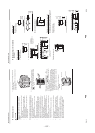
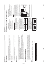
Super Digital Inverter
Single system, Twin system, Triple system
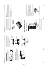
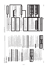
Stripping length power cord and connecting wire
WARNING
Be sure to attach the provided clamp filter to the power supply wire in order to conform to EMC standards.
123
L1
L2 L3 N
Indoor/outdoor
connecting wire
Power supply wire
Cord clampCord clamp
Earth screw
Clamp filter
(accessory)
Cord clampCord clamp
Earth screw
50
10
(mm)
10
50
10
40
1
2
3
10
40
L1L2L3N
Earth line
Connecting wire Power supply wire
Earth line