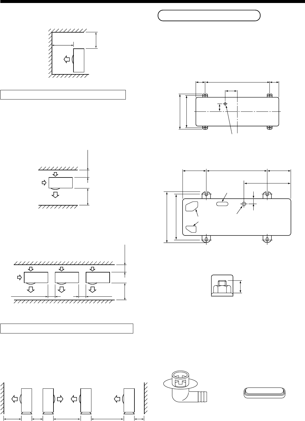
40
1000
or more
300
or more
1500
or more
2000
or more
200
or more
300
or more
300
or more
1000
or more
200
or more
1000
or more
1000
or more
1000
or more
150
or more
<Obstacle also at the upper side>
Obstacles at both front and rear sides
Open the upper side and both right and left sides.
The height of obstacle at both front and rear side,
should be lower than the height of the outdoor unit.
<Standard installation>
1. Single unit installation
2. Serial installation of two or more units
Serial installation at front and rear sides
Open the upper side and both right and left sides.
The height of obstacle at both front and rear sides
should be lower than the height of the outdoor unit.
<Standard installation>
600
115
90 90
310
76
330
Ø28 Drain hole
600150 150
430
365
40
400
Drain hole
Knockout hole
Drain nipple mounting hole
Drain nipple Waterproof rubber cap
Installation of Outdoor Unit
• Before installation, check strength and horizontality of
the base so that abnormal sound does not generate.
• According to the following base diagram, fix the base
firmly with the anchor bolts.
(Anchor bolt, nut: M10 x 4 pairs)
<SM560AT-E>
15 or less
<SM800AT-E, SP560AT-E, SP800AT-E>
Set the out margin of the anchor bolt to 15mm or less.
• In case of draining through the drain hose, attach the
following drain nipple and the waterproof rubber cap,
and use the drain hose (Inner diam.: 16mm) sold on
the market. And also seal the screws securely with
silicone material, etc. so that water does not drop
down. Some conditions may cause dewing or drip-
ping of water.
3
SELECTION OF INSTALLATION


