46
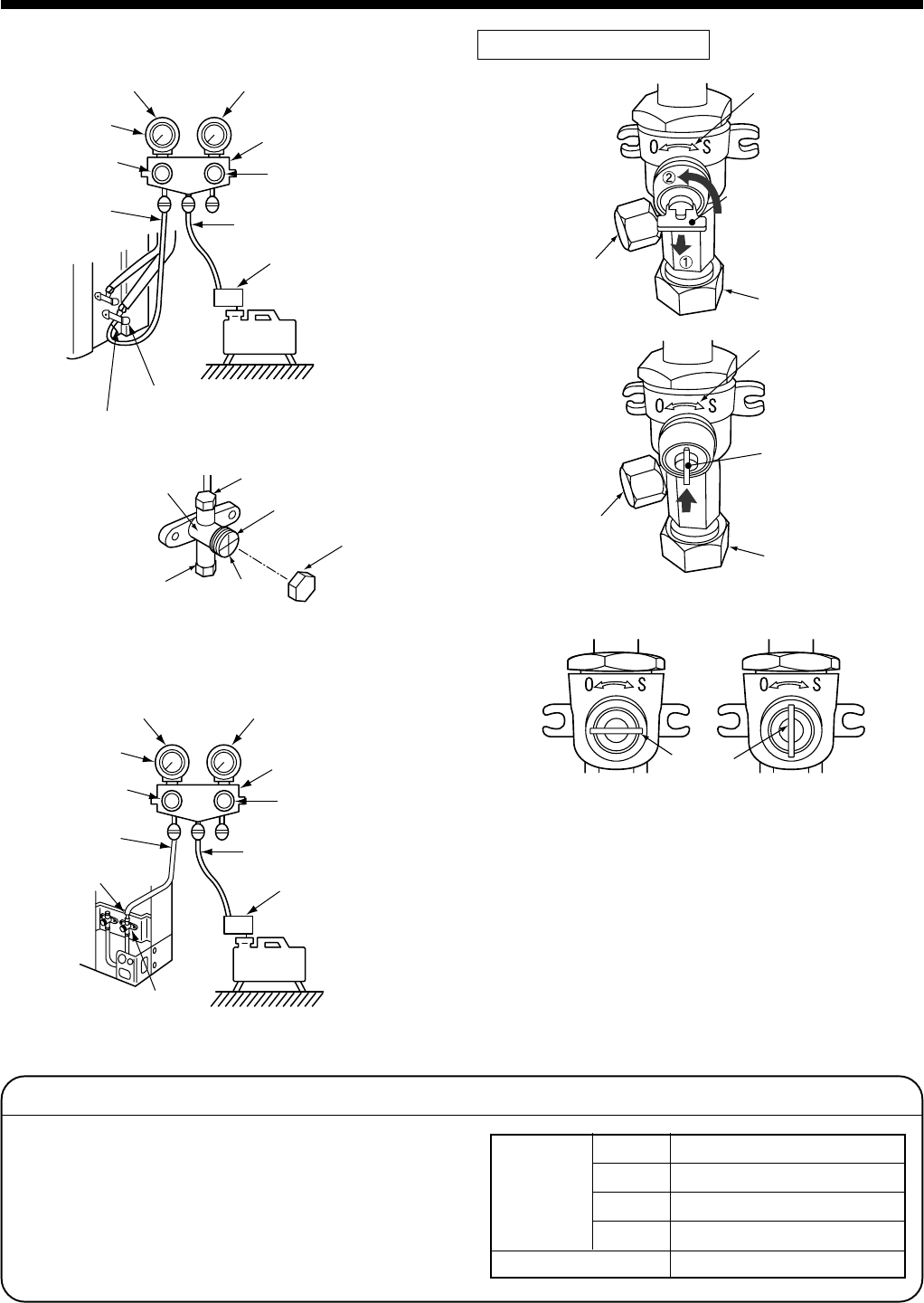
Compound pressure gauge
Service port (Valve core (Setting pin))
Packed valve (Gas side)
Pressure gauge
Manifold valve
Handle Hi
(Keep fully closed)
Charge hose
(For R410A only)
Vacuum pump adapter
for counter-flow prevention
(For R410A only)
Handle Lo
Charge hose
(For R410A only)
–101kPa
(–76cmHg)
Vacuum
pump
Valve rod
Valve unit
Flare nut
Stopper
Charge port
Charge cap
Service port
(Valve core (Setting pin))
Compound pressure gauge
Packed valve at gas side
Pressure gauge
Manifold valve
Handle Hi
(Keep fully closed)
Charge hose
(For R410A only)
Vacuum pump adapter
for counter-flow prevention
(For R410A only)
Handle Lo
Charge hose
(For R410A only)
–101kPa
(–76cmHg)
Vacuum
pump
<SM560AT-E>
<SM800AT-E, SP560AT-E, SP800AT-E>
Valve unit
Valve unit
Charge port
Charge port
Handle
Pull out the handle and
using cutting pliers, etc.
turn it counterclockwise
by 90˚. (Open fully)
Flare nut
Flare nut
Push in handle.
Closed completely
Handle
Opened fully
How to open the valve
Handle position
*1. Use the vacuum pump, vacuum pump adapters,
and gauge manifold referring to the manuals
attached to each tool before using them. For the
vacuum pump, check oil is filled up to the specified
line of the oil gauge.
*2. While the air is purged, check again that the
connecting port of charge hose, which has a
projection to push the valve core, is firmly con-
nected to the charge port.
Valve handling precautions
• Open the valve stem or the handle until it strikes
the stopper. It is unnecessary to apply further
force.
• Securely tighten the cap with a torque wrench.
• Cap tightening torque
5
EVACUATING
Ø6.4
Valve size
Ø9.5
Ø12.7
Ø15.9
Charge port
14 to 18N•m (1.4 to 1.8kgf•m)
33 to 42N•m (3.3 to 4.2kgf•m)
33 to 42N•m (3.3 to 4.2kgf•m)
20 to 25N•m (2.0 to 2.5kgf•m)
14 to 18N•m (1.4 to 1.8kgf•m)


