


– 116 –
No.
6
Part name
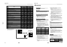
Interface board
(Control board)
MCC-1599
Procedure
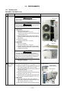
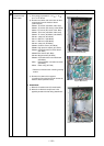
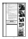
1. Detachment
1) Carry out the operation in 1. of
Q
, 1. of
R
and 1. of
T
above.
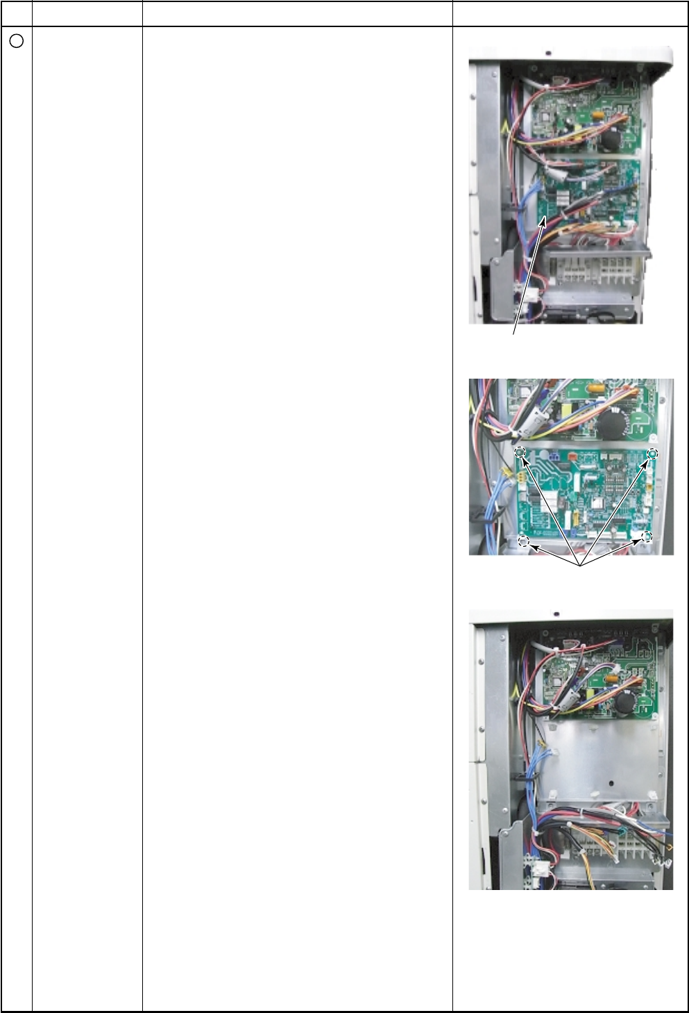
2) Remove lead wires and connectors to other
components from the interface board
(control board).
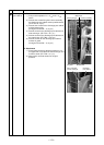
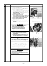
CN603: TD sensor (3P: White, tube: Red)
CN602: TO sensor (2P: Orange, tube: Black)
CN601: TE sensor (2P: Green, tube: Blue)
CN600: TS sensor (3P: White, tube: Gray)
CN604: TL sensor (2P: White, tube: White)
CN700: 4-way coil (2P: Yellow)
CN710: PMV coil 1 (6P: White)
CN711: PMV coil 2 (6P: White)
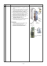
CN702: 2-way coil (3P: White)
CN606: Pressure sensor (4P: White)
CN690: High pressure switch (3P: Green)
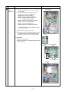
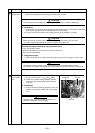
CN802: Connection with Fan IPDU board
(5P: white)
CN609: Case thermo.(2P :Blue)
CN708: Magnet switch (2P: Blue)
CN608: Connection with noise filter board
(2P: White)
CN01 : Indoor/Outdoor connection terminal
(5P: White)
CN02 : Power relay (3P: Red)
∗ Remove connectors after unlocking housing
section
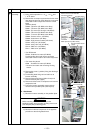
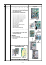
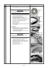
3) Remove the claws of the supports
(4 positions) fixing the board and remove the
interface board (Control board).
2. Attachment
1) Mount the interface board (Control board).
2) Mount the individual components in the
opposite procedure to that during detachment.
Remarks
Interface board (Control board)
Support (4 positions)
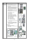
Statue of control board when removed