


– 107 –
EN 21
Digital Inverter
13
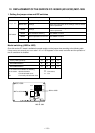
FUNCTIONS TO BE IMPLEMENTED LOCALLY
Handling Existing Pipe
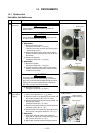
When using the existing pipe, carefully check for the
following:
• Wall thickness (within the specified range)
• Scratches and dents
• Water, oil, dirt, or dust in the pipe
• Flare looseness and leakage from welds
• Deterioration of copper pipe and heat insulator
• Before recovering the refrigerant in the existing system,
perform a cooling operation for at least 30 minutes.
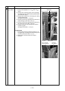
Cautions for using existing pipe
• Do not reuse a flare nut to prevent gas leaks.
Replace it with the supplied flare nut and then process it
to a flare.
• Blow nitrogen gas or use an appropriate means to keep
the inside of the pipe clean. If discolored oil or much
residue is discharged, wash the pipe.
• Check welds, if any, on the pipe for gas leaks.
• There may be a problem with the pressure resistance of
the branching pipes of the existing piping. Replace them
with branch pipes (sold separately).
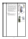
When the pipe corresponds to any of the following, do not
use it. Install a new pipe instead.
• The pipe has been opened (disconnected from indoor
unit or outdoor unit) for a long period.
• The pipe has been connected to an outdoor unit that
does not use refrigerant R22, R410A or R407C.
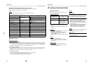
• The existing pipe must have a wall thickness equal to or
larger than the following thicknesses.
• Do not use any pipe with a wall thickness less than these
thicknesses due to insufficient pressure capacity.
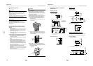
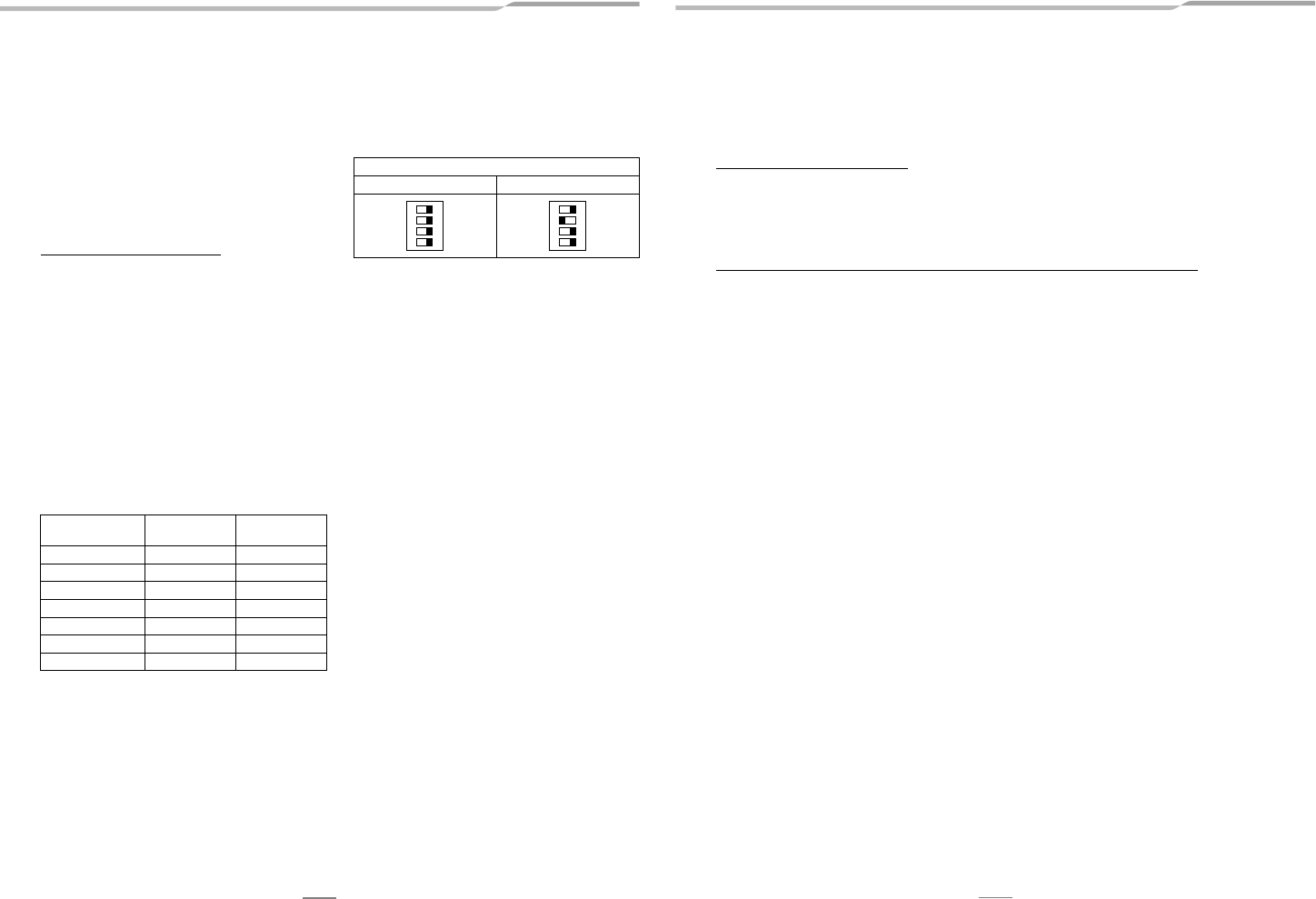
• When using a Ø19.1 mm gas pipe for the existing piping,
set bit 3 of SW802 (switch for existing pipe) on the P.C.
board of the outdoor unit to ON. In this case, the heating
performance may be reduced depending on the outside
air temperature and room temperature.
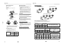
Recovering Refrigerant
Use the refrigerant recovery equipment to recover the
refrigerant.
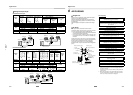
Reference outside
diameter (mm)
Wall thickness
(mm)
Material
6.4 0.8 —
9.5 0.8 —
12.7 0.8 —
15.9 1.0 —
19.1 1.2 —
22.2 1.0 Half hard
28.6 1.0 Half hard
SW802
When shipped from factory When using existing pipe
1234
ON
1234
ON
22 EN
Digital Inverter
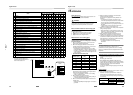
14
TROUBLESHOOTING
You can perform fault diagnosis of the outdoor unit with the LEDs on the P.C. board of the outdoor unit in addition to using the
check codes displayed on the wired remote controller of the indoor unit.
Use the LEDs and check codes for various checks. Details of the check codes displayed on the wired remote controller of the
indoor unit are described in the Installation Manual of the indoor unit.
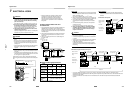
Verifying current abnormal status
1. Check that DIP switch SW803 is set to OFF.
2. Jot down the states of LED800 to LED804. (Display mode 1)
3. Press SW800 for at least 1 second. The LED status changes to display mode 2.
4. Check the code whose display mode 1 equals the LED states jotted down and display mode 2 equals the current flashing
status of LED800 to LED804 from the following table to identify the cause.
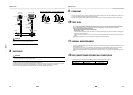
Verifying an abnormal state in the past although the abnormal state no longer occurs
1. Set bit 1 of DIP switch SW803 to ON.
2. Jot down the states of LED800 to LED804. (Display mode 1)
3. Press SW800 for at least 1 second. The LED status changes to display mode 2.
4. Find an error whose display mode 1 equals the LED states jotted down and display mode 2 equals the current flashing
states of LED800 to LED804 from the following table to identify the error.
• An outside air temperature (TO) sensor error can be checked only while it occurs.