


– 103 –
EN 13
Digital Inverter
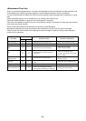
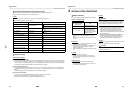
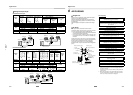
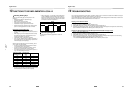
Refrigerant Pipe Length
Simultaneous twin, triple
Simultaneous double twin
Outdoor
unit
Allowable pipe length (m) Height difference (m)
Total length
• 1 + 2
• 1 + 3
• 1 + 4
Maximum
Branch piping
• 2
• 3
• 4
Maximum
Branch piping
• 3 – 2
• 4 – 2
• 4 – 3
Maximum
Indoor-outdoor H
Indoor-indoor
('h)
Indoor unit:
Upper
Outdoor unit:
Upper
SM2244 70 20 10 30 30 0.5
SM2804 70 20 10 30 30 0.5
Outdoor
unit
Pipe diameter (mm)
Number of bent
portions
Main pipe Branch piping
Gas side Liquid side Gas side Liquid side
SM2244 Ø28.6 Ø12.7 Ø15.9 Ø9.5 10 or less
SM2804 Ø28.6 Ø12.7 Ø15.9 Ø9.5 10 or less
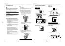
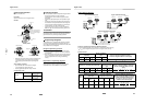
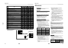
Outdoor
unit
Allowable pipe length (m) Height difference (m)
Total length
• 1 + 2 + 4
• 1 + 2 + 5
• 1 + 3 + 6
• 1 + 3 + 7
Maximum
Branch
piping
• 4
• 5
• 6
• 7
Maximum
Branch
piping
• 4 + 2
• 5 + 2
• 6 + 3
• 7 + 3
Maximum
Branch piping
• ( 4 + 2) – ( 5 + 2)
• ( 4 + 2) – ( 6 + 3)
• ( 4 + 2) – ( 7 + 3)
• ( 5 + 2) – ( 6 + 3)
• ( 5 + 2) – ( 7 + 3)
• ( 6 + 3) – ( 7 + 3)
Maximum
Indoor-outdoor H
Indoor-
indoor
('h)
Indoor
unit:
Upper
Outdoor
unit:
Upper
SM2244 70 15 20 6 30 30 0.5
SM2804 70 15 20 6 30 30 0.5
Outdoor
unit
Pipe diameter (mm)
Number of bent
portions
Main pipe Branch piping
Gas side Liquid side Gas side Liquid side
SM2244 Ø28.6 Ø12.7
2, 3: Ø15.9
4, 5, 6, 7: Ø12.7
2, 3: Ø9.5
4, 5, 6, 7: Ø6.4
10 or less
SM2804
Ø28.6 Ø12.7 2 to 7: Ø15.9 2 to 7: Ø9.5 10 or less
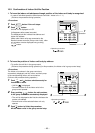
3
2
4
1
H
2
3
H
1
Figure of Simultaneous twin
Indoor Unit
Indoor Unit
Outdoor Unit
Indoor Unit
Indoor Unit
Outdoor Unit
Indoor Unit
Figure of Simultaneous triple
45
2
1
3
67
H
Figure of Simultaneous double twin
Indoor Unit
Indoor Unit
Outdoor Unit
Indoor Unit
Indoor Unit
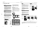
14 EN
Digital Inverter
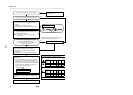
6 AIR PURGING
Airtight Test
Before starting an airtight test, further tighten the spindle
valves on the gas side and liquid side.
Pressurize the pipe with nitrogen gas charged from the
service port to the design pressure (4.15 MPa) to conduct
the airtight test.
After the airtight test is completed, evacuate the nitrogen
gas.
Air Purge
With respect to the preservation of the terrestrial
environment, adopt “Vacuum pump” to purge air (Evacuate
air in the connecting pipes) when installing the unit.
• Do not discharge the refrigerant gas to the atmosphere to
preserve the terrestrial environment.
• Use a vacuum pump to discharge the air (nitrogen, etc.)
that remains in the set. If air remains, the capacity may
decrease.
For the vacuum pump, be sure to use one with a backflow
preventer so that the oil in the pump does not backflow into
the pipe of the air conditioner when the pump stops.
(If oil in the vacuum pump is put in an air conditioner
including R410A, it may cause trouble with the refrigeration
cycle.)
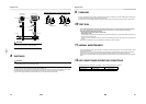
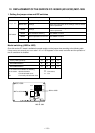
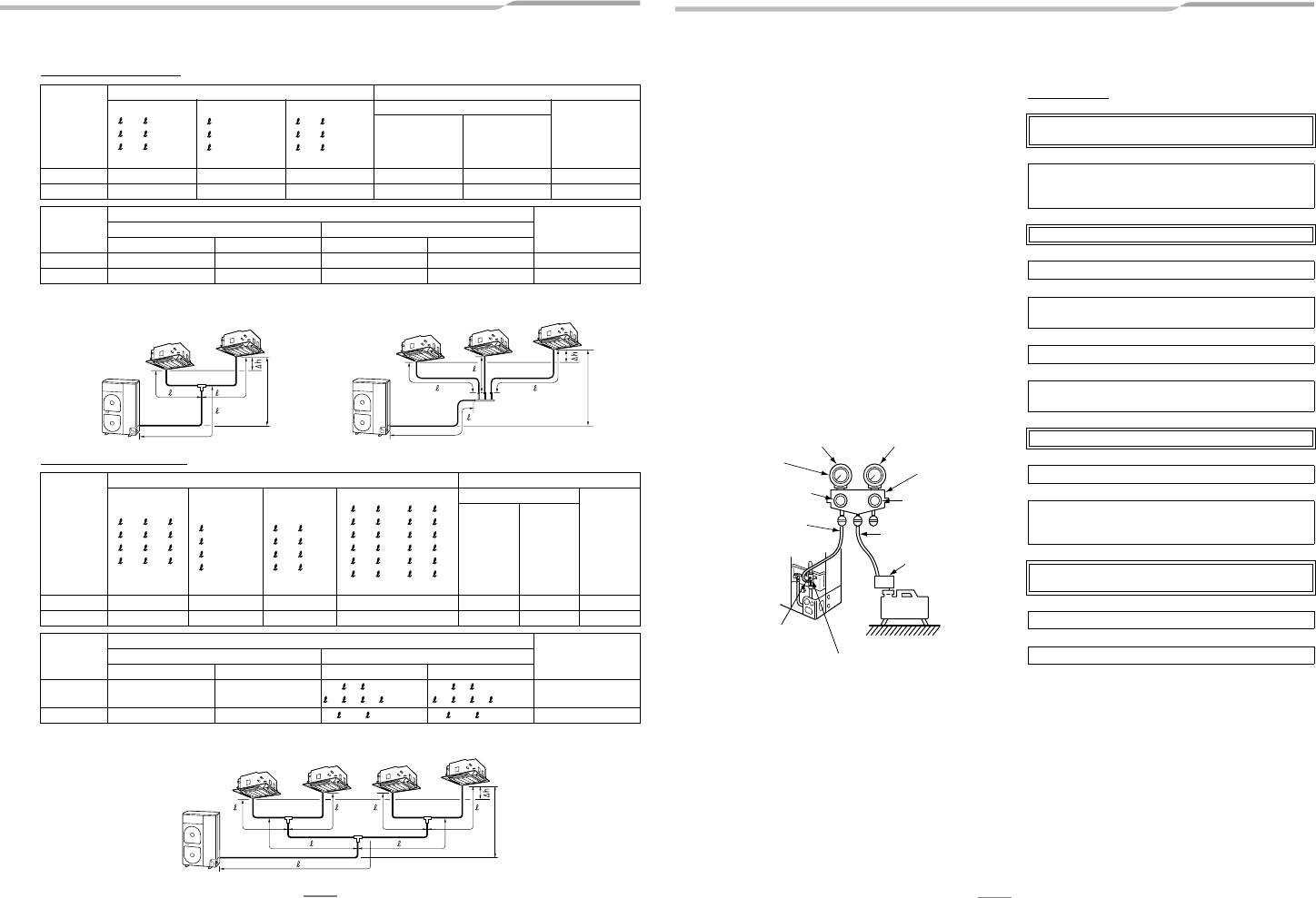
Vacuum pump
*1
Use the vacuum pump, vacuum pump adapter, and gauge
manifold correctly referring to the manuals supplied with each
tool before using them.
Check that the vacuum pump oil is filled up to the specified line
of the oil gauge.
*2
When air is not charged, check again whether the connecting
port of the discharge hose, which has a projection to push the
valve core, is firmly connected to the charge port.
Pressure gauge
Gauge manifold valve
Handle High
(Keep fully closed)
Compound pressure gauge
Charge hose
(For R410A only)
Vacuum pump adapter
for counter-flow
prevention
(For R410A only)
–101 kPa
(–76 cmHg)
Handle Low
Charge hose
(For R410A only)
Charge port
(Valve core (Setting pin))
Packed valve at gas side
Vacuum
pump
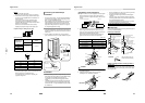
As shown in the figure, connect the charge hose after the
manifold valve is closed completely.
L
Attach the connecting port of the charge hose with a
projection to push the valve core (setting pin) to the charge
port of the set.
L
Open Handle Low fully.
L
Turn ON the vacuum pump. (*1)
L
Loosen the flare nut of the packed valve (Gas side) a little to
check that the air passes through. (*2)
L
Retighten the flare nut.
L
Execute vacuuming until the compound pressure gauge
indicates –101 kPa (–76 cmHg). (*1)
L
Close Handle Low completely.
L
Turn OFF the vacuum pump.
L
Leave the vacuum pump as it is for 1 or 2 minutes, and
check that the indicator of the compound pressure gauge
does not return.
L
Open the valve stem or valve handle fully. (First, at liquid
side, then gas side)
L
Disconnect the charge hose from the charge port.
L
Tighten the valve and caps of the charge port securely.