


– 102 –
EN 11
Digital Inverter
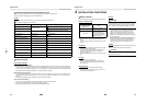
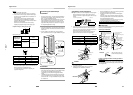
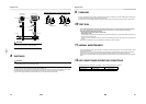
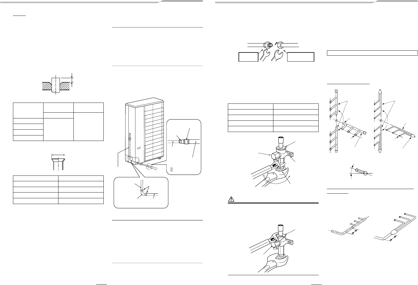
Flaring
1. Cut the pipe with a pipe cutter.
Be sure to remove burrs that may cause a gas leak.
2. Insert a flare nut into the pipe, and then flare the pipe.
Use the flare nuts supplied with the air conditioner or
those for R410A.
Insert a flare nut into the pipe, and flare the pipe.
As the flaring sizes of R410A differ from those of
refrigerant R22, the flare tools newly manufactured for
R410A are recommended.
However, the conventional tools can be used by
adjusting the projection margin of the copper pipe.
Projection margin in flaring: B (Unit: mm)
Rigid (Clutch type)
Flaring diameter size: A (Unit: mm)
* In case of flaring for R410A with the conventional flare
tool, pull the tool out approx. 0.5 mm more than that for
R22 to adjust it to the specified flare size.
The copper pipe gauge is useful for adjusting the
projection margin size.
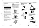
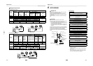
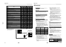
Connecting the Gas Side Pipe
REQUIREMENT
• Be sure to use the Ø19.1 mm pipe and joint provided as
accessories of the outdoor unit to connect the gas side
Ø19.1 mm pipe and Ø28.6 mm pipe.
• When leading out the pipes toward the front, to one of the
sides or toward the rear, use the Ø19.1 mm pipe and
elbow provided as accessories of the outdoor unit, and
adjust the bending direction. Cut the Ø19.1 mm pipe to
the required length before using it.
1. Align the provided Ø19.1 mm pipe with the pipe lead-out
direction, and shape it so that its end comes out from the
outdoor unit.
2. On the outside of the outdoor unit, use the provided
joints, and braze the Ø19.1 mm pipe and Ø28.6 mm pipe.
REQUIREMENT
• Before proceeding to weld the refrigerant pipe, be sure to
pass nitrogen through the pipe to prevent oxidation inside
it. If nitrogen is not passed through the pipe, the
refrigerating cycle may become clogged by oxidized
scales.
• The Ø28.6 mm pipe cannot be passed through the pipe
cover and knockout hole in the base plate so be sure to
connect the Ø19.1 mm pipe and Ø28.6 mm pipe outside
the outdoor unit.
Outer diam. of
copper pipe
R410A tool used
Conventional tool
used
R410A
1.0 to 1.5
9.5
0 to 0.5
12.7
15.9
19.1
Outer diam. of copper pipe A
9.5 13.2
12.7 16.6
15.9 19.7
19.1 24.0
B
A
+0
–0.4
Ø19.1 mm pipe
(accessory)
Ø19.1 mm pipe
(accessory)
Brazing
Elbow (accessory) Ø19.1 mm pipe
(accessory)
Ø19.1 mm pipe
(accessory)
Ø28.6 mm pipe
(procured locally)
Joint
(accessory)
Joint (accessory)
: Brazing
12 EN
Digital Inverter
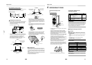
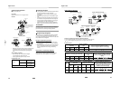
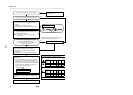
Tightening of Connecting Part
1. Align the centers of the connecting pipes and fully tighten
the flare nut with your fingers. Then fix the nut with a
wrench as shown in the figure and tighten it with a torque
wrench.
2. As shown in the figure, be sure to use two wrenches to
loosen or tighten the flare nut of the valve on the gas
side. If you use a single crescent, the flare nut cannot be
tightened to the required tightening torque.
On the other hand, use a single crescent to loosen or
tighten the flare nut of the valve on the liquid side.
(Unit: N•m)
CAUTION
1. Do not put the crescent wrench on the cap or cover.
The valve may break.
2. If applying excessive torque, the nut may break
according to some installation conditions.
• After the installation work, be sure to check for gas leaks
of the pipe connections with nitrogen.
• Pressure of R410A is higher than that of R22 (Approx.
1.6 times).
Therefore, using a torque wrench, tighten the flare pipe
connecting sections that connect the indoor/outdoor units
at the specified tightening torque.
Incomplete connections may cause not only a gas leak,
but also trouble with the refrigeration cycle.
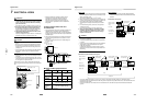
Branch Pipe
Carry out the refrigerant piping work using the branch pipe kit
which is purchased separately.
Branch pipe installation
Length of straight sections on main pipe side of
branch pipe
Provide a straight section with a length of at least 500 mm on
the main pipe side of the branch pipe. (Same for both liquid
side and gas side)
Outer dia. of copper pipe Tightening torque
9.5 mm (diam.) 33 to 42 (3.3 to 4.2 kgf•m)
12.7 mm (diam.) 50 to 62 (5.0 to 6.2 kgf•m)
15.9 mm (diam.) 68 to 82 (6.8 to 8.2 kgf•m)
19.1 mm (diam.) 100 to 120 (10.0 to 12 kgf•m)
Half union or packed valve Flare nut
Externally
threaded side
Internally threaded
side
Fix with wrench. Tighten with torque wrench.
Cover
Piping valve
Tightened
Flare nut
Cap
Loosened
Valve at gas side
NO GOOD
Cover
Cap
Do not apply refrigerant oil to the flared surface.
The ends of the branch pipes
form a line perpendicular to
the ground.
Both the collecting
pipe and branch
pipes form a line
parallel to the ground.
Collection area
Collecting pipe
Branch pipe
Make sure that the pipes are
installed level after branching.
Inclined
The ends of the branch
pipes form a line
perpendicular to the ground.
Both the collecting
pipe and branch
pipes form a line
parallel to the ground.
Branch pipe
Liquid sideGas side
NO GOOD
500 mm
or more
500 mm
or more