


– 25 –
Concealed Duct High Static Pressure
Installation Manual
8 ELECTRICAL CONNECTION
WARNING
1. Using the specified wires, ensure to connect
the wires, and fix wires securely so that the
external tension to the wires do not affect the
connecting part of the terminals.
Incomplete connection or fixation may cause a fire,
etc.
2. Be sure to connect earth wire. (grounding
work)
Incomplete grounding cause an electric shock.
Do not connect ground wires to gas pipes, water
pipes, lightning rods or ground wires for telephone
wires.
3. Appliance shall be installed in accordance with
national wiring regulations.
Capacity shortage of power circuit or incomplete
installation may cause an electric shock or a fire.
CAUTION
• If incorrect/incomplete wiring is carried out, it will cause
an electrical fire or smoke.
• Be sure to install an earth leakage breaker that is not
tripped by shock waves.
If an earth leakage breaker is not installed, an electric
shock may be caused.
• Be sure to use the cord clamps attached to the product.
• Do not damage or scratch the conductive core and inner
insulator of power and inter-connecting wires when
peeling them.
• Use the power cord and Inter-connecting wire of
specified thickness, type, and protective devices
required.
REQUIREMENT
• For power supply wiring, strictly conform to the Local
Regulation in each country.
• Power supply for indoor unit must be exclusive and
separated from the one for outdoor unit.
• For wiring of power supply of the outdoor units, follow the
Installation Manual of each outdoor unit.
• Never connect 220–240V power to the terminal blocks
( , , etc.) for control wiring.
(Otherwise, the system will fail.)
• Perform the electric wiring so that it does not come to
contact with the high-temperature part of the pipe.
The coating may melt resulting in an accident.
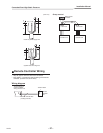
• After connecting wires to the terminal blocks, provide a
trap and fix wires with the cord clamp.
• Run the refrigerant piping line and control wiring line in
the same line.
• Do not turn on the power of the indoor unit until
vacuuming of the refrigerant pipes completes.
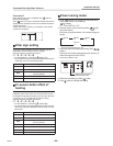
Remote controller wiring
2-core non polarity wire is used for the remote controller
wiring.
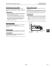
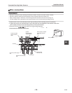
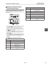
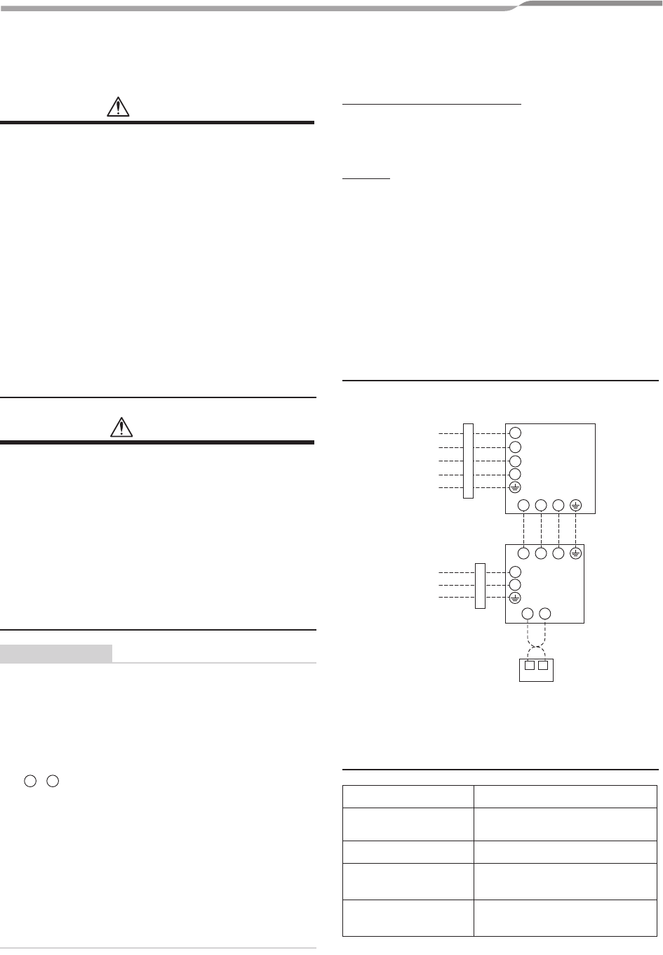
Wiring
1. Figure below shows the wiring connections indoor
power line and between the indoor and outdoor units
and between the indoor units and remote controller.
The wires indicated by the dash lines are provided at
the installation place.
2. Insulate the unsheathed redundant cords (conductors)
with electrical insulation tape.
Process them so that they do not touch any electrical or
metal parts.
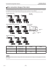
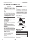
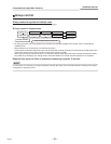
Wiring diagram
Power and Wiring
Specification
*Number of wire x wire size
A B
Indoor fan Power supply
220-240V~, 50 Hz
Maximum running
current
15A
Fuse rating
25A
Indoor fan power supply
wire*
3 x 2.5mm
2
or more
(H07 RN-F or 60245 IEC 66)
System interconnecting
wires*
4 x 1.5mm
2
or more
(H07 RN-F or 60245 IEC 66)
L
2
L
3
L
1
N
L
N
1 2 3
A B
1 2 3
Outdoor
unit
Indoor
unit
Indoor Fan Input power
220-240V~, 50 Hz
Outdoor Input power
380-415V 3N~, 50 Hz
Circuit breaker
(Leakage breaker)
Circuit breaker
(Leakage breaker)
Wired remote
controller
25-EN