


– 105 –
EN 17
Digital Inverter
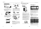
7 ELECTRICAL WORK
WARNING
1. Using the specified wires, ensure that the wires are
connected, and fix wires securely so that the external
tension to the wires does not affect the connecting
part of the terminals.
Incomplete connection or fixation may cause a fire, etc.
2. Be sure to connect the earth wire (grounding work).
Incomplete grounding may lead to electric shock.
Do not connect ground wires to gas pipes, water pipes,
lightning rods or ground wires for telephone wires.
3. The appliance shall be installed in accordance with
national wiring regulations.
Capacity shortages of the power circuit or an incomplete
installation may cause an electric shock or fire.
CAUTION
• Wrong wiring may cause a burn-out of some electrical
parts.
• Be sure to use the cord clamps attached to the product.
• Do not damage or scratch the conductive core or inner
insulator of the power and inter-connecting wires when
peeling them.
• Use the power and Inter-connecting wires with specified
thicknesses, specified types and protective devices
required.
• Remove the panel, and you can see electric parts on the
front side.
• A metal pipe can be installed through the hole for wiring.
If the hole size does not fit the wiring pipe to be used, drill
the hole again to an appropriate size.
Furthermore, be sure to secure these wires with the pipe
valve fixing plate and cord clamps stored in the electric parts
box.
• When the outdoor air temperature drops, power is
supplied to the compressor with the purpose of
preheating the compressor in order to protect it.
Therefore, leave the main power switch at the “on”
setting during the periods when the air conditioner is
being used.
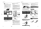
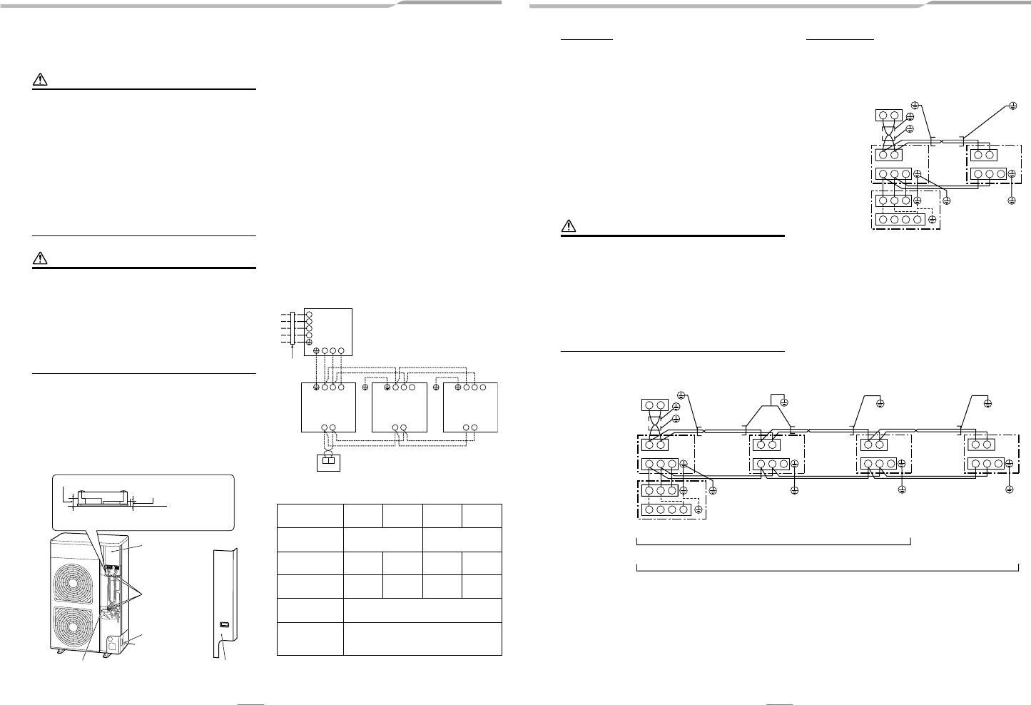
Wiring between Indoor Unit and
Outdoor Unit
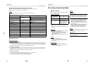
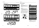
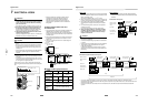
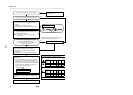
1. Figure below shows the wiring connections between the
standard indoor and outdoor units and between the
indoor units and remote controller. The wires indicated by
the broken lines or dot-and-dash lines are provided at the
installation place.
2. Refer to the wiring diagrams of the models concerned for
the internal wiring connections of the outdoor unit and
indoor units.
3. There is no need to perform the P.C. board settings for
the indoor units.
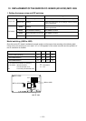
Power and Wiring Specifications
* Number of wire u wire size
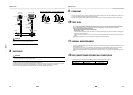
Electric parts box
Cord clamp
Pipe hole
PanelPipe valve fixing plate
• Secure the indoor/outdoor connecting wires at side C.
Side D (Space: 8.5 mm)
Side C (Space: 4 mm)
Model
(RAV-SM Type)
224AT8 280AT8 224AT7 280AT7
Power supply
380-415 V 3N~
50 Hz
380 V 3N~
60 Hz
Maximum
running current
18.0 A 22.0 A 18.0 A 22.0 A
Installation
fuse rating
25 A 25 A 25 A 25 A
Power wire*
5 u 2.5 mm
2
or more
(H07 RN-F or 60245 IEC 66)
Indoor/outdoor
connecting
wires*
4 u 1.5 mm
2
or more
(H07 RN-F or 60245 IEC 66)
1 2
A B
31 2
A B
3
1 2 3
L1
L2
L3
Ν
1 2
A B
3
Outdoor unit
Remote
controller
Indoor unit
(main)
Leakage
breaker
Input power
380-415 V 3N~, 50Hz
380 V 3N~, 60Hz
Indoor unit
(secondary)
Indoor unit
(secondary)
18 EN
Digital Inverter
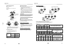
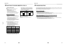
How to wire
1. Connect the connecting wire to the terminal as identified
with their respective numbers on the terminal block of the
indoor and outdoor units.
H07 RN-F or 60245 IEC 66 (1.5 mm
2
or more)
2. When connecting the connecting wire to the outdoor unit
terminal, prevent water from coming into the outdoor unit.
3. Secure the power supply wire and indoor/outdoor
connecting wires using the cord clamp of the outdoor
unit.
4. For interconnecting wires, do not use a wire joined to
another on the way.
Use wires long enough to cover the entire length.
5. Wiring connections differ in conformance to EMC
standards, depending whether the system is twin,
triple or double twin. Connect wires according to
respective instructions.
CAUTION
• An installation fuse must be used for the power supply
line of this air conditioner.
• Incorrect/incomplete wiring may lead to an electrical fire
or smoke.
• Prepare an exclusive power supply for the air conditioner.
• This product can be connected to the mains power.
Fixed wire connections:
A switch that disconnects all poles and has a contact
separation of at least 3 mm must be incorporated in the
fixed wiring.
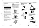
Wiring diagram
* For details on the remote controller wiring/installation,
refer to the Installation Manual enclosed with the remote
controller.
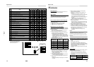
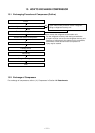
Simultaneous twin system
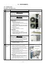
Simultaneous triple and double twin system
* Use 2-core shield wire (MVVS 0.5 to 2.0 mm
2
or more) for the remote controller wiring in the simultaneous twin,
simultaneous triple and simultaneous double twin systems to prevent noise problems. Be sure to connect both ends of the
shield wire to earth leads.
* Connect earth wires for each indoor unit in the simultaneous twin, simultaneous triple and simultaneous double twin
systems.
A B
1 2 3
A B
1
1
L1 L2 NL3
2
2
3
3
Remote controller
Remote controller
wiring
Indoor side
Indoor/Outdoor
connecting wires
Outdoor side
Indoor
side
Remote controller
inter-unit wiring
Indoor power
inter-unit wiring
380-415 V 3N~, 50Hz
380 V 3N~, 60Hz
A B
1 2 3
A B
1 2 3
A B
1 2 3
A B
1 2 3
1
L1 L2 NL3
2 3
Remote controller
Remote controller
wiring
Indoor side
Indoor/Outdoor
connecting wires
Outdoor side
Remote controller
inter-unit wiring
Indoor power
inter-unit wiring
Remote controller
inter-unit wiring
Indoor power
inter-unit wiring
Indoor side Indoor side
380-415 V 3N~, 50Hz
380 V 3N~, 60Hz
Remote controller
inter-unit wiring
Indoor power
inter-unit wiring
Indoor side
Triple
Double twin