


– 101 –
10 EN
Digital Inverter
5
REFRIGERANT PIPING
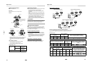
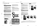
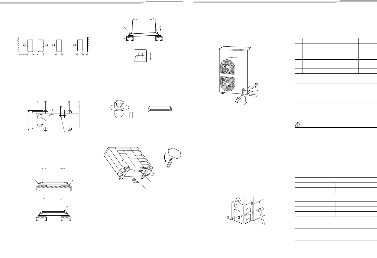
Knockout of Pipe Cover
Knockout procedure
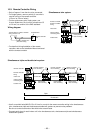
• The indoor/outdoor connecting pipes can be connected
in 4 directions.
Take off the knockout part of the pipe cover through
which pipes or wires will pass through the base plate.
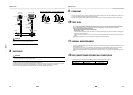
• Detach the pipe cover and tap on the knockout section a
few times with the shank of a screwdriver. A knockout
hole can easily be punched.
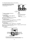
• As shown in the figure below, it is easier to punch out the
knockout hole when the pipe cover is left in place rather
than when the cover is removed from the unit.
In knocking out the hole, the knockout section can easily
be removed by hand once the bottom of the three
locations where the section is joined along the guide lines
is broken using a screwdriver.
• After punching out the knockout hole, remove burrs from
the hole, and install the protective bush and guard
material around the passage hole provided as
accessories in order to protect the wires and pipes. Also
be sure to attach the pipe covers after connecting the
pipes. The pipe covers can be easily attached by cutting
off the slits at the lower part of the covers.
* Be sure to wear heavy work gloves while working.
Optional Installation Parts
(Locally procured)
REQUIREMENT
Follow the instructions in the installation manual provided
with the branch pipe kit and the instructions in the installation
manual of the indoor unit to connect the refrigerant pipe
between the branch pipe and indoor unit.
Refrigerant Piping Connection
CAUTION
TAKE NOTE OF THESE 4 IMPORTANT POINTS BELOW
FOR PIPING WORK
1. Keep dust and moisture away from inside the connecting
pipes.
2. Tightly connect the connection between pipes and the
unit.
3. Evacuate the air in the connecting pipes using a
VACUUM PUMP.
4. Check for gas leaks at connection points.
Piping connection
REQUIREMENT
On the gas side, be sure to use the Ø19.1 mm pipe provided
with the outdoor unit.
Rear direction
Pipe cover
Side direction
Down direction
Front direction
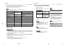
Parts name Q’ty
A
Refrigerant piping
Liquid side: Ø12.7 mm
Gas side: Ø19.1 mm (Approx. 800 mm)
Ø28.6 mm
One each
B
Pipe insulating material
(polyethylene foam, 10 mm thick)
1
C Putty, PVC tape One each
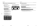
Liquid side
Outer diameter Thickness
Ø12.7 mm 0.8 mm
Gas side
Outer diameter Thickness
Ø19.1 mm 1.2 mm
Ø28.6 mm 1.0 mm (half hard)
EN 9
Digital Inverter
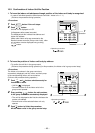
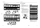
Serial installation in front and rear
Open above and to the right and left of the unit.
The height of an obstacle in both the front and rear of the unit
should be lower than the height of the outdoor unit.
Standard installation
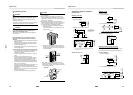
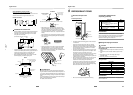
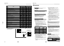
Installation of Outdoor Unit
• Before installation, check the strength and horizontalness
of the base so that abnormal sounds do not emanate.
• According to the following base diagram, fix the base
firmly with the anchor bolts.
(Anchor bolt, nut: M10 x 4 pairs)
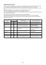
• As shown in the figure below, install the foundation and
vibration-proof rubber pads to directly support the bottom
surface of the fixing leg that is in contact with and
underneath the bottom plate of the outdoor unit.
* When installing the foundation for an outdoor unit with
downward piping, consider the piping work.
Set the out margin of the anchor bolt to 15 mm or less.
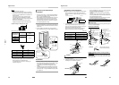
• When water is to be drained through the drain hose,
attach the following drain nipple and waterproof rubber
cap, and use the drain hose (Inner diam: 16 mm) sold on
the market. Also seal the knockout hole and screws
securely with silicone material, etc., to prevent water from
leaking.
Some conditions may cause dewing or dripping of water.
• When collectively draining discharged water completely,
use a drain pan.
• Please pay attention to the drain in region with snowfall
and cold temperature, as it may be frozen and cause
drainage problems. Punch the knockout holes on the
base plate to improve drainability. Use a screwdriver and
take off the knockout part outward.
For Reference
If a heating operation is to be continuously performed for a
long time under the condition that the outdoor temperature is
0 °C or lower, draining defrosted water may be difficult due to
the bottom plate freezing, resulting in trouble with the cabinet
or fan.
It is recommended to procure an anti-freeze heater locally in
order to safely install the air conditioner.
For details, contact the dealer.
1,000 or
more
300 or
more
1,500 or
more
2,000 or
more
200 or
more
150 150600
430
40
365
400
Drain nipple mounting hole
Drain hole
Knockout
hole
GOOD
Fixing leg
Absorb vibration
with vibration-proof
rubber pads
Foundation
GOOD
Bottom plate of
outdoor unit
Foundation
Support the bottom surface of the
fixing leg that is in contact with and
underneath the bottom plate of the
outdoor unit.
NO GOOD
If only the end of the
fixing leg is supported,
it may deform.
Do not support the
outdoor unit only
with the fixing leg.
Foundation
15 or less
Drain nipple
Waterproof rubber cap
(1 pc.)
Waterproof rubber cap
Drain nipple
Knockout hole