


80
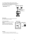
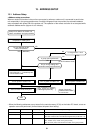
Remote
controller
Central
control
remote
controller
Indoor unit
Indoor
unit
Network
adapter
Indoor
control
P.C. board
X Y
A B
Indoor
control
P.C. board
A B
Indoor
unit
Indoor
control
P.C. board
A B
Indoor
unit
Indoor
control
P.C. board
A B
Indoor unit
Indoor
unit
Network
adapter
Indoor
control
P.C. board
X Y
A B
Indoor
control
P.C. board
A B
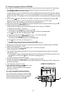
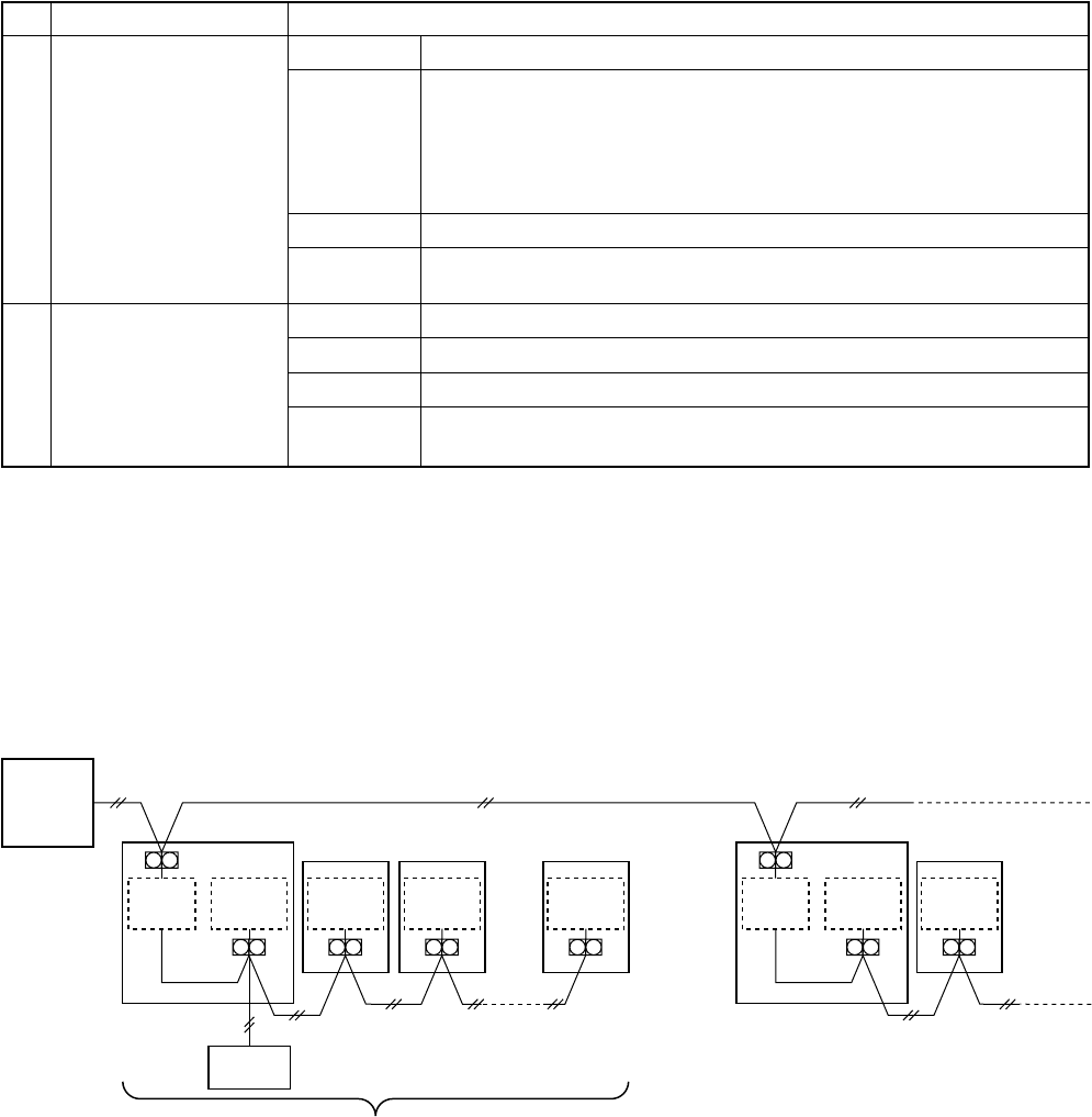
Connectable indoor units per group: Up to 8 units
(1-remote controller system*)
* In case of 2-remote controllers system,
the connectable indoor units are up to 7 units.
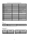
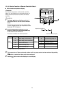
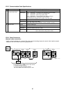
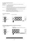
12-2-5. Communication Cable Specifications
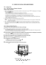
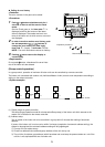
12-2-6. Cable Connection
<Network cable connection>
• Install a network adapter per 1 group of the group control (including single unit control). Also install a network
adapter to one of the indoor units in the group control.
No.
1
2
Communication circuit
Remote controller
communication side
AI NET side
Communication cable specifications
Cable
Cable type
Cable dia.
Cable length
Cable
Cable type
Cable dia.
Cable length
Neutral 2-cable type
CVV (JIS C3401) Controlling vinyl insulation vinyl seal cable
VCTF (JIS C3306) Vinyl cab tire round type cord
VCT (JIS C3401) 600V vinyl cab tire cable
VVR (JIS C3401) Vinyl insulation seal cable round type
MVVS Cable with net shielding for instrumentation
CPEVS Shielded polyethylene insulation vinyl seal cable
0.5 to 2.0 mm²
Total cable length Max. 500m
(Up to 400m when there is wireless remote controller in group)
Neutral 2-cable type
MVVS Cable with net shielding for instrumentation
1.25 mm² ≤ 500 m, 2.0 mm² ≤ 1 km
Total cable length : Up to 500m when using 1.25mm² cable,
Up to 1000m when using 2.0mm² cable