


101
P.C. board
base
Inverter box (Metal sheet)
Inverter
control
P.C. board
assembly
Cycle control
P.C. board
assembly
Cycle control
P.C. board
assembly
Inverter
control
P.C. board
assembly
Inverter
control
P.C. board
assembly
Groove for
P.C. boaed
Heat sink
Inverter box
(Metal sheet)
No.
Part name
Control P.C.
board
assembly
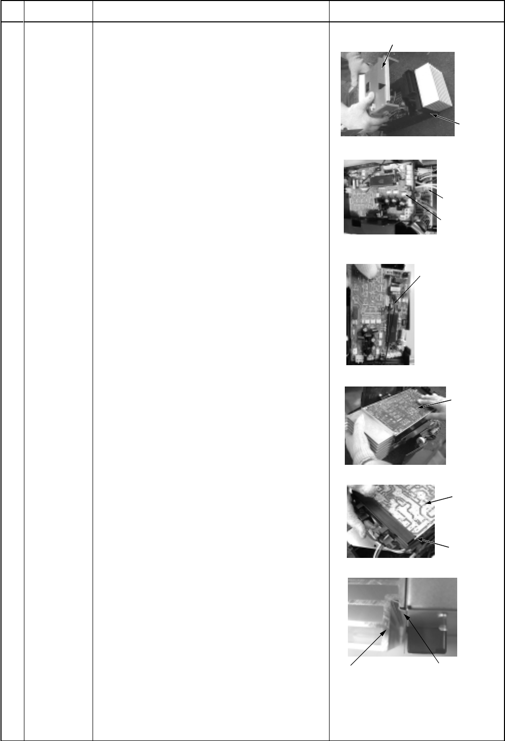
Procedure
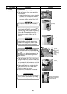
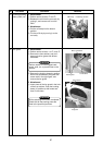
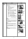
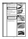
1) Remove the inverter box from P.C. board base.
2) Disconnect lead wires and connectors con-
nected from the control P.C. board assembly to
other parts.
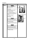
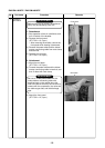
1. Lead wires:
With the power terminal block: 2 pcs.
(Single phase) (Red, White)
With the compressor: 3 pcs.
(Red, White, Black)
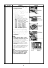
2. Connectors
CN301 : Outdoor fan (3P, White) *Note 1)
CN300 : Position detection (5P, White)
CN700 : 4-way valve (3P, Yellow) *Note 1)
CN702 : PMV coil (6P, White)
CN600 : TD sensor (3P, White)
CN605 : TS sensor (3P, White) *Note 1)
CN604 : TE sensor (2P, White) *Note 1)
CN601 : TO sensor (2P, White)
CN02 : Indoor/Outdoor connecting
terminal block (2P, Black)
CN500 : Case thermo (2P, White) *Note 1)
CN14, CN15 : Reactor (3P, Relay
connector, Blue) *Note 1)
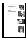
*Note 1)
Remove the connector while releasing locking of
the housing.
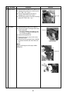
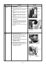
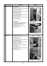
3) Remove the control P.C. board assembly from
P.C. board base. (Remove the heat sink and
the inverter control P.C. board assembly as
they are screwed.)
Note 2)
Remove the heat sink upward by taking off two
claws of P.C. base and holding the heat sink.
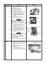
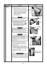
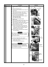
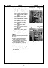
4) Take off three screws fixing the heat sink to the
control P.C. board assembly.
5) Mount a new control P.C. board assembly.
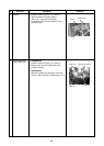
Note 3)
When mounting a new board, check that it is
correctly set in the groove of the base holder of
P.C. board base.
Remarks