


– 85 –
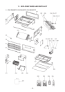
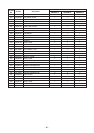
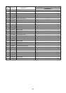
No. Part name Procedure Remarks
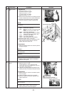
1. Detachment
1) Perform works of 1 of c.
(In case of under air intake)
Perform works of 1 of
d.
(In case of back air intake)
Perform works of 1 of
e.
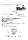
2) Remove the indoor/outdoor connecting wire and
remote controller wire from each terminal block.
3) Remove the connectors which connected
from the control P.C. board to other parts.
NOTE
First unlock the housing and then remove the
connectors.
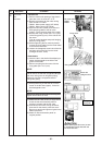
CN34 : Float switch (3P, Red)
CN41 : Remote controller terminal block (3P,
Blue)
(Screw part of terminal block, 2P.)
CN504 : Drain pump (2P, White)
CN67 : Power supply terminal block (5P: Black)
(Screw part of terminal block, 3P.)
CN101 : TC sensor (2P: Black)
CN102 : TCJ sensor (2P, Red)
CN104 : Room temperature (2P, Yellow)
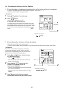
4) Remove screws. (Ø4 x 10, 2 pcs.)
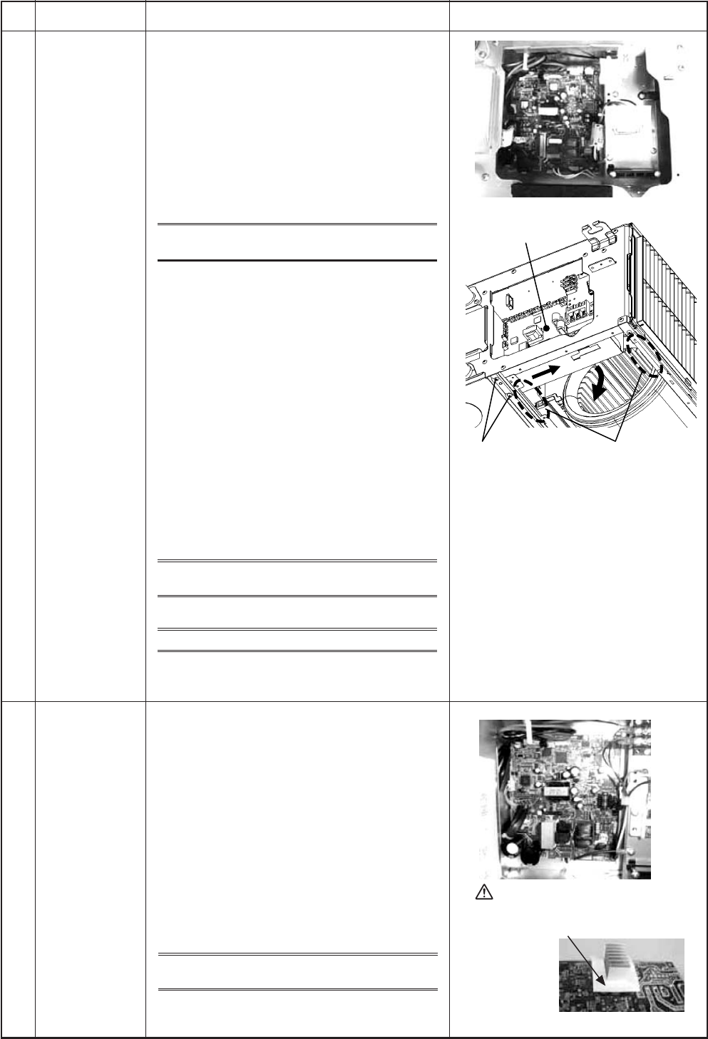
5) Slide the electric parts box toward the arrow
mark and then remove the box from the
bottom side of the main unit.
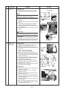
2. Attachment
1) Attach the electric parts box and then perform
wiring as original.
Notes 1
Check there is no missing or contact failure on
the connectors.
Notes 2
Be sure to perform wiring as original.
2) Attach air filter, suction panel, and electric
parts box as original.
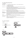
Electric parts
box
f
Electric parts box
Screw Notch part
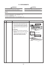
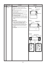
1. Detachment
1) Perform work of 1 of f.
(In the works of 1 of
f, removal of the
control P.C. board is available even if you do
not perform works after 4)).
2) Unlock the card edge spacers (5 positions) in the
electric parts box to remove the control P.C. board.
2. Attachment
1) Mount control P.C. board in the electric parts
box as original.
2) Attach the electric parts box as original.
3) Be sure to perform wiring as original in the
electric parts box.
NOTE
Check there is no missing or contact failure on
the connectors.
4) Attach each air filter, suction panel or
electric parts box cover as original.
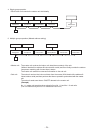
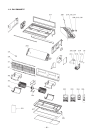
Control P.C.
board
g
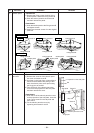
CAUTION
When replacing PC. board,
check no-mex paper is attached.