


– 144 –
P.C. board
base
Inverter box (Metal sheet)
Inverter
control
P.C. board
assembly
Cycle control
P.C. board
assembly
Cycle control
P.C. board
assembly
No.
Part name
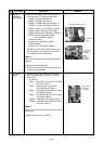
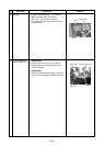
Inverter
assembly
(Continued)
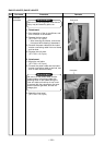
Cycle P.C.
board
Procedure
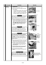
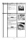
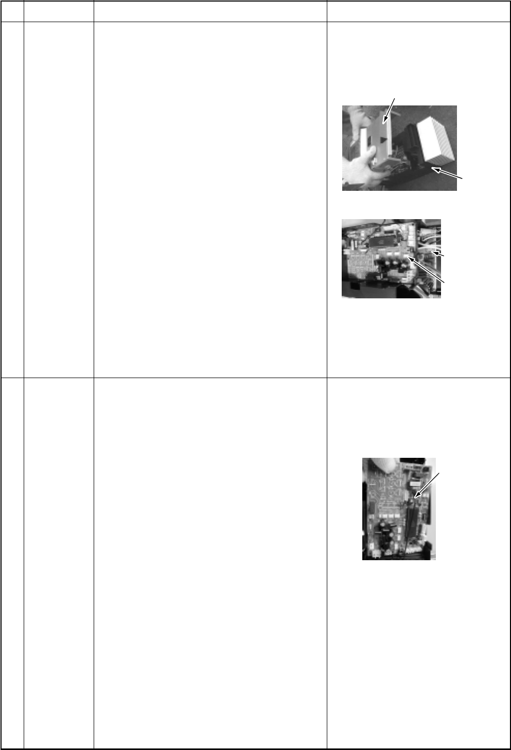
7) Remove connectors which are connected
from the cycle P.C. board to other parts.
CN600: TD sensor (3P: White)
CN601: TO sensor (2P: White)
CN604: TE sensor (2P: White) *Note 1)
CN605: TS sensor (3P: White) *(Note 1)
CN301: Outdoor fan (3P: White) *(Note 1)
CN300: Position detection (5P: White)
CN500: Case thermo. (2P: Blue) *(Note 1)
CN702: P.M.V. (Pulse Motor Valve)
coil (6P: White) *(Note 1)
Relay connector:
4-way valve (3P: Yellow) *(Note 1)
Relay connector:
Reactor 2 pcs. (2P: White) *(Note 1)
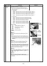
Compressor lead: Remove terminal cover of
the compressor, and remove the lead wire
from terminal of the compressor.
*(Note 1)
Remove the connectors by releasing lock of the
housing.
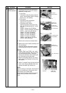
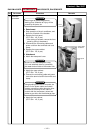
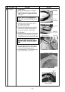
8) Remove various lead wires.
9) Cut off tie lap which fixes various lead wires
to the inverter assembly.
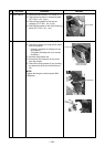
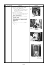
1) Remove connectors and lead wires which
are connected from the cycle P.C. board to
other parts.
1. Connector
CN01 : Connection with IPDU P.C. board
(5P, Red) *(Note 1)
CN02 : Indoor/Outdoor connection
terminal block (5P, Black)
CN03 : Connection with IPDU P.C. board
(3P, White) *(Note 1)
CN04 : Connection with IPDU P.C. board
(2P, White) *(Note 1)
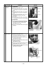
CN700 : 4-way valve (3P, Yellow) *(Note 1)
CN800 : Connection with IPDU P.C. board
(5P, Red) *(Note 1)
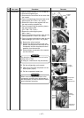
*(Note 1)
Remove the connector while releasing locking of
the housing.
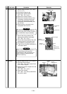
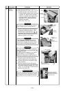
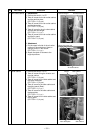
2) Mount a new cycle P.C. board.
Remarks