


– 187 –
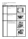
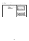
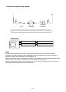
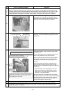
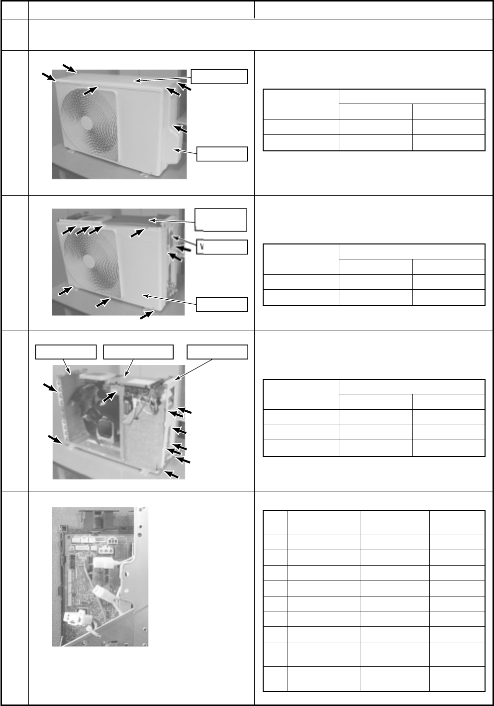
4. Cord heater installation work procedure
Upper cabine
t
Valv
e
c
ov
er
W
irin
g
cove
r
Water-proof
cover
Front
c
a
b
in
et
Side cabinet
(
L
)
Side cabinet
(
R
)
Inverter assembl
y
No.
1
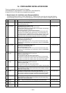
Procedure
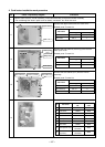
Remove each cabinet, inverter assembly, motor base assembly, and partition board assembly.
* Do not damage the electric parts such as cables, connectors, etc. while this work.
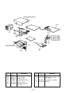
Remove the upper cabinet and the valve cover.
Related parts / Screws list
Photo / Explanatory diagram
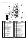
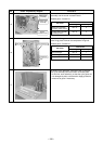
Remove the front cabinet, the wiring cover and the
water-proof cover.
Related parts / Screws list
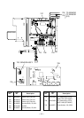
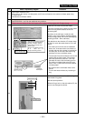
Remove the side cabinet (R/L) and the inverter
assembly.
Related parts / Screws list
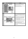
Remove the inverter assembly.
1-1
1-2
1-3
1-4
No.
1
2
3
4
5
6
7
8
9
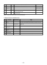
Part name
TE sensor
TD sensor
TO sensor
TS sensor
4-way valve coil
PMV coil
Fan motor
Compressor lead
Reactor
(2 pieces.)
Connector
No.
CN600
CN601
CN602
CN603
CN701
CN700
CN300
(Intermediate
connector)
(Intermediate
connector)
Connector
color
White
White
White
White
Yellow
White
White
White
White
Part name
Side cabinet (R)
Side cabinet (L)
Inverter assembly
Used screw
Screw type Quantity
Ø4 × 87
Ø4 × 83
Ø4 × 81
Part name
Front cabinet
Wiring cover
Used screw
Screw type Quantity
Ø4 × 87
Ø4 × 82
Part name
Upper cabinet
Valve cover
Used screw
Screw type Quantity
Ø4 × 85
Ø4 × 11