


– 113 –
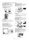
4. Wiring Specifications
• Use 2-core with no polar wire.
• Match the length of wire to wire length of the central
control system.
If mixed in the system, the wire length is
lengthened with all indoor/outdoor inter-unit wire length at side.
• To prevent noise trouble, use 2-core shield wire.
• Connect the shield wire by closed-end connection and apply open process (insulating process) to the last terminal.
Ground the earth wire to 1 point at indoor unit side. (In case of central controlling of digital inverter unit setup)
No. of wires
2
Size
Up to 1000m: twisted wire 1.25mm
2
Up to 2000m: twisted wire 2.0mm
2
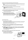
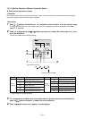
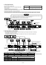
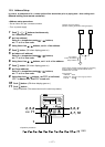
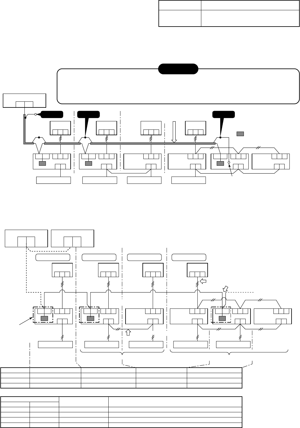
5. P.C. Board Switch (SW01) Setup
When performing collective control by customized setup only, the setup of terminator is necessary.
• Using SW01, set up the terminator.
• Set up the terminator to only the adapter connected to the indoor unit of least line address No.
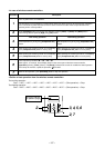
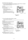
Central control device
U1
U3
U2
U4
Central control device
U1
U3
123
U2
U4
Central control devices: Max. 10 units
Refrigerant line 1
Outdoor unit
Indoor unit
12
3
Refrigerant line 2
12
3
Refrigerant line 3
12
3
Refrigerant line 4
123
A
B
U3
U4 123
A
B
U3
U4 123
A
B
123
A B
123
A B
123
A B
U3 U4
TCC-LINK adapter
This product
sold separately
( )
Remote controller
Indoor/outdoor inter-unit wire (AC230V serial)
Central control system wiring
Master unit
Master
unit
Sub unit Sub unit
Sub
unit
* Wiring for No.1 and 2 only
Remote controller Remote controller Remote controller Remote controller
Remote controller wiring
Group operation (Max. 8 units) Twin/Triple operation (Example of triple)
(OFF at shipment from factory)
(OFF at shipment from factory)
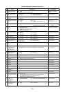
Line address
SW01 Bit 1
SW01 Bit 2
Remarks
1
ON
OFF
Turn SW01 Bit 1 to ON.
2
OF
OFF
As status shipped from factory
4
OF
OFF
As status shipped from factory
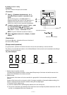
(Reference) Setup contents of switch
SW01
Bit 1
OFF
ON
OFF
ON
Bit 1
OFF
OFF
ON
ON
Terminator
None
100Ω
75Ω
43Ω
Remarks
Mixed with multi (Link wiring) at shipment from factory
Central control by digital inverter only
Spare
Spare
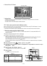
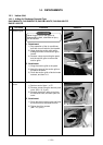
Central control device
U1
U2
123
Outdoor unit
Indoor unit
123123123
123
A
B
U3
U4 123
A
B
U3
U4 123
A
B
123
A B
123
A B
123
A B
U3
U4
Caution 1
Remote controller
Central control system wiring
Master unit
Master
unit
Sub unit Sub unit
Sub unit
Caution 2
Remote controller Remote controller Remote controller
(Group operation) (Triple operation)
Caution 3
: TCC-LINK adapter
(This option)
Earth terminal
CAUTION
1) Closed-end connection of shield wire (Connect all the connecting parts of each indoor unit)
2) Apply open process to the last terminal (insulating process).
3) Ground earth wire to 1 point at indoor unit side.