


– 59 –
10-5. Test Operation
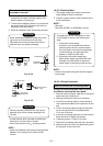
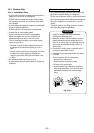
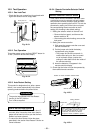
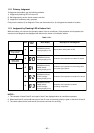
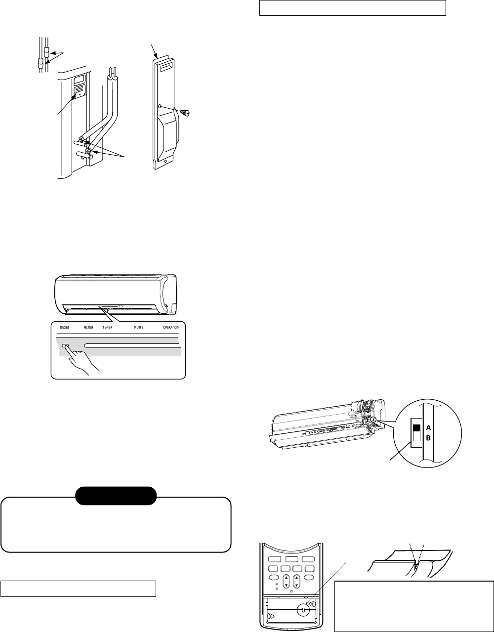
10-5-1. Gas Leak Test
• Check the flare nut connections for gas leaks with
a gas leak detector and/or soapy water.
Fig. 10-5-1
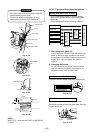
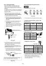
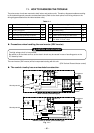
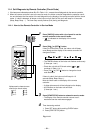
10-5-2. Test Operation
To test the system, press and hold RESET button for
10 sec. (There will be one short beep.)
Fig. 10-5-2
10-5-3. Auto Restart Setting
This product is designed so that, after a power
failure, it can restart automatically in the same
operating mode as before the power failure.
Information
The product was shipped with Auto Restart
function in the OFF position.
Turn it ON as required.
How to Set the Auto Restart
• Press and hold the RESET button for about 3
seconds. After 3 seconds, three short electric
beeps will be heard to inform you that the Auto
Restart has been selected.
• To cancel the Auto Restart, follow the steps
described in the section Auto Restart Function on
Owner’s Manual.
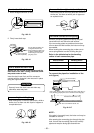
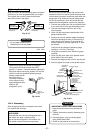
10-5-4. Remote Controller Selector Switch
Setting
Remote controller selector switch
• If two indoor units are installed in the same room
or adjoining rooms, the second unit can inadvert-
ently receive a remote controller signal and start
operation when operating the first unit. This can be
prevented by setting one of the indoor units and
the corresponding remote controller to the B
setting (the A setting is the default setting).
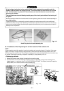
1. Setting the selector switch on the main unit
• Remove the front panel, and then set the
selector switch to “B”.
• After making the switch setting, remount the
front panel.
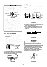
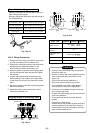
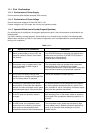
2. Setting the remote controller
1) Slide open the remote controller cover and
remove the batteries.
2) Cut the jumper wire inside the battery
compartment using nippers.
• The jumper wire should not remain in
contact after being cut. Also, be careful
not to let plastic scraps, jumper wire
cuttings or other debris enter the inside of
the remote controller.
3) Insert the batteries. “B” appears in the
remote controller display.
3. Check that the indoor unit can be operated by
the modified remote controller.
Check places for
flare nut connections
(indoor unit)
Check places
for outdoor unit
Valve cover
Electric parts
Fig. 10-5-3
Fig. 10-5-4
Position of remote controller selector switch
Selector switch
CLOCK
CHECK
RESET
CLR
SET
SWING
FIX
FAN
ON
OFF
HiPOWER
ECO
MEMO
SLEEP
1
.
3
.
5
.
9H
When switching between settings “A” and
“B”, always switch the indoor unit board
and the remote controller as a pair.
(Otherwise, the indoor unit will not
accept the remote controller’s signals.)
Jumper wire
Cutting direction