


Appendix-7
Appendix
No. Photo / Explanatory diagram Procedure
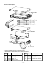
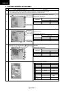
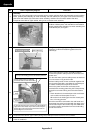
2-4
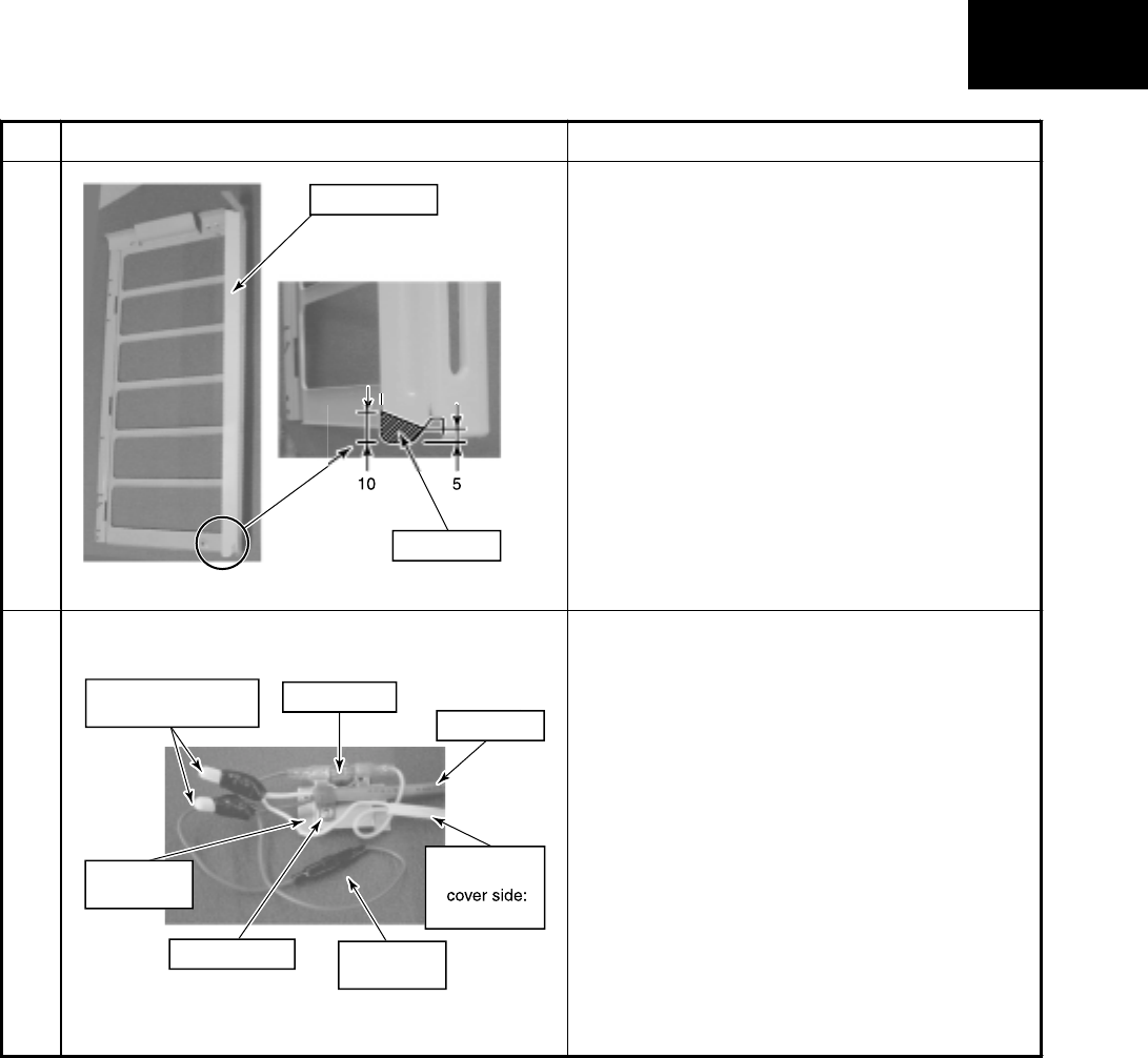
Rework the side cabinet (L) to remove part of it.
The area to be removed is indicated by the shaded
lines in the left figure.
After removing part of the side cabinet (L), deburr the
edges of the side cabinet (L).
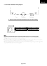
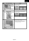
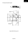
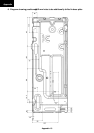
2-5
Perform end process and bundling of each cable.
Using fixing screws (Self-tapping screw type-B Ø3.5
× 6mm), fix the thermostat to the thermostat fixing
plate.
Perform end process for various lead cables and
connect them according to the wiring diagram.
Attach #250 Faston and UL-approved sleeves each
to the end of lead cables which are connected to the
thermostat.
Using insulation tape, apply protective measures to
the connected parts by the close-end connectors.
Using P-shape clamp and the screws (Self-tapping
screw type-B Ø4 × 8mm), fix the power cord to the
thermostat fixing plate.
When the power cord size does not match with P-
shape clamp, procure the most appropriate one at
the local site.
F
use
Fuse holde
r
Thermostat
Th
e
rmo
s
t
a
t
fixin
g
plat
e
P-shape clamp
Pow
e
r
c
or
d
C
ord heate
r
* Transparent
L
s
i
de
Close-end connector
insulation tap
e
D
e
l
e
t
e
Side cabinet
(
L
)