– 43 –
Item
4. Capacity
control
Operation flow and applicable data, etc.
Description
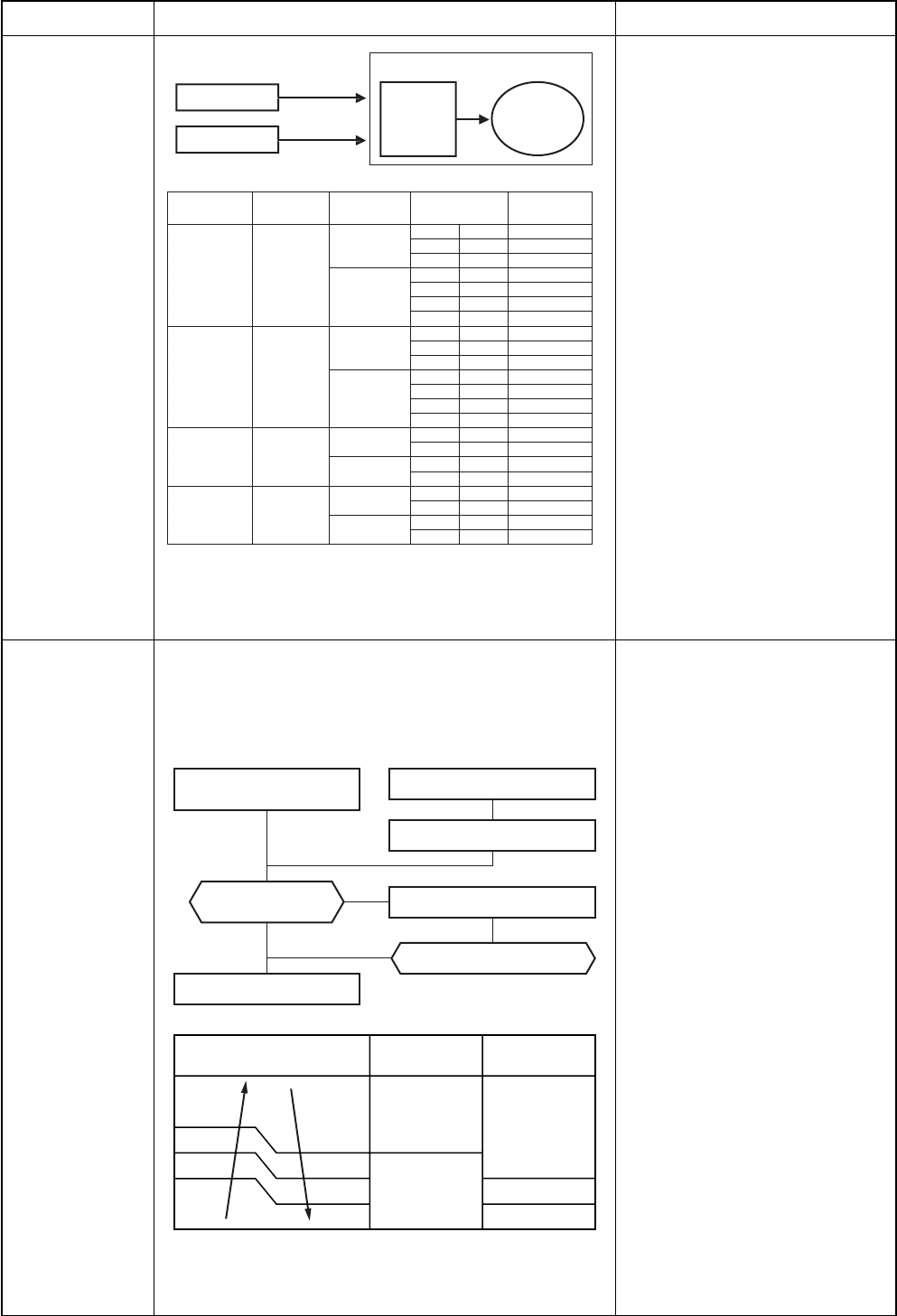
1) Indoor unit A and Indoor unit B
determine the respective
instruction revolutions from the
difference between the remote
controller setting temperature
(Ts) and the indoor temperature
(Ta), and transmit this to the
outdoor unit.
2) The outdoor unit receives the
instructions from the indoor
units, and the inverter operates
the compressor at the calculated
revolutions.
3) The compressor operation range
in each operating mode is shown
in the left table.
This function prevents troubles on the electronic parts of
the compressor driving inverter.
This function also controls drive circuit of the compressor
speed so that electric power of the compressor drive circuit
does not exceed the specified value.
1) The input current of the outdoor
unit is detected in the inverter
section of the outdoor unit.
2) According to the detected
outdoor temperature, the
specified value of the current is
selected.
3) Whether the current value
exceeds the specified value or
not is judged.
4) If the current value exceeds the
specified value, this function
reduces the compressor speed
and controls speed up to the
closest one commanded from
the indoor unit within the range
which does not exceed the
specified value.
5. Current release
control
Outdoor temp. To
Setup of current release point
Capacity control continues.
Outdoor temp.
40˚C
7.5A
12.0A
10.1A
10.3A
10.5A
16˚C 39˚C
11˚C 15.5˚C
10.5˚C
Cooling current
release value
Heating current
release value
Current decrease
Outdoor unit inverter main
circuit control current
High
Low
Reduce compressor speed
Operating current ≤
Setup value
Outdoor unit
Op
eration
m
o
de
N
o.o
f
operating unit
C
ombination of
in
d
oor
u
nit
s
C
om
p
ressor
r
evolution
(
r
p
s
)
M18EAV-
E
M18EA
C
V-
E
C
oolin
g
1 unit
10
–
13
to 4
5
13
–
13
to 7
1
1
6
–
1
3 to 79
2 units
1 unit
2 units
1 unit
2 units
1 unit
2 units
10
10
15
to
83
13
10
1
5 to
83
13
1
3
15
to
83
16
10
15
to
83
M18EAV-
E
Heatin
g
10
–
1
3 to 7
6
13
–
13
to
99
16
–
13
to
102
10
1
0
15 to 12
0
13
10
15
to
120
13
1
3
15 to 12
0
16
1
0
1
5
to 12
0
M14EAV-
E
M14EA
C
V-
E
C
ooling
10
–
13
to 5
6
13
–
1
3 to 74
10
10
18
to 7
4
13
10
18
to 75
M14EAV-
E
Heatin
g
10
–
13
to 7
5
13
–
13
to
80
10
1
0
1
6 to 84
13
10
16
to
85
I
n
d
oor
U
n
i
t
A
I
n
d
oor
U
n
i
t
A
In
Outdoor unit
verter
C
ompressor


