


– 52 –
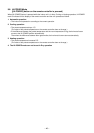
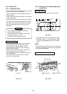
CAUTION
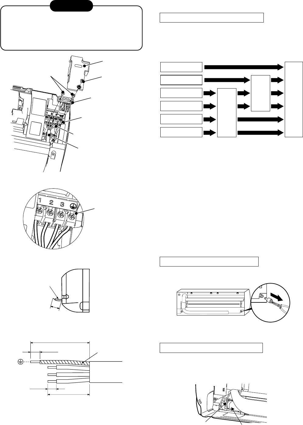
• Be sure to refer to the wiring system diagram
labeled inside the front panel.
• Check local electrical regulations for any
specific wiring instructions or limitations.
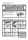
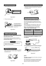
10-3-5. Piping and Drain Hose Installation
Piping and drain hose forming
• Since condensation results in machine trouble,
make sure to insulate both the connecting pipes
separately.
(Use polyethylene foam as insulating material.)
Fig. 10-3-6
Fig. 10-3-7
Fig. 10-3-8
Fig. 10-3-9
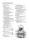
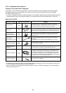
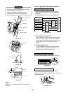
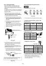
NOTE :
WIRE TYPE : more than H07 RN-F or 245 IEC 66.
(1.0mm²)
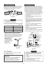
Screw
Screw
Terminal cover
Cord clamp
Terminal block
Earth wire
Connecting cable
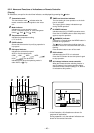
Terminal block
Connecting cable
About 15 cm
Earth line
70 mm
10 mm
10 mm
50 mm
Fig. 10-3-10
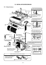
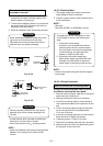
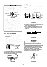
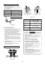
1. Die-cutting front panel slit
Cut out the slit on the left or right side of the front
panel for the left or right connection and the slit
on the bottom left or side of thefront panel for the
bottom left or right connection with a pair of
nippers.
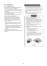
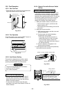
2. Changing drain hose
For left connection, left-bottom connection and
rear-left connection’s piping, it is necessary to
relocate the drain hose and drain cap.
How to remove the drain cap
Clip drain cap with needle-nose pliers, and pull out.
Fig. 10-3-11
How to remove the drain hose
The drain hose is secured in place by a screw.
Remove the screw securing the drain hose, then pull
out the drain hose.
Die-cutting
Front panel slit
Changing
drain hose
Piping preparation
Rear right
Rear left
Bottom left
Left
Bottom right
Right
Screw
Drain hose
Fig. 10-3-12