


Appendix
Appendix-6
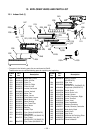
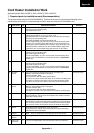
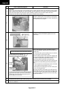
No. Photo / Explanatory diagram Procedure
2
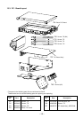
Cord heater installation work
Drill a hole on the outdoor unit base plate, and fix the cord heater to the outdoor unit base plate using P-shape
clamp.
Connect the cord heater cables.
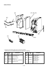
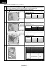
2-1
Using a motor drill, etc., drill Ø3.2 holes on the outdoor unit base plate. (12 positions) See Appendix-10 for the
additional hole positions.
These holes are used to fix the cord heater to the outdoor unit base plate with P-shape clamp.
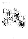
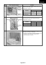
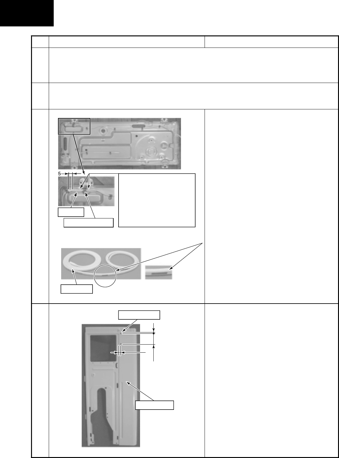
2-2
Insert the PVC tube into the cord heater.
This tube is designed to protect the cord heater from
the fixing screws used to secure the anchoring feet.
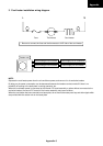
As shown in the left figure, install the cord heater
(1.5m) to the outdoor unit base plate by using P-
shape clamp and screws (Self-tapping screw type-B
Ø4 × 6mm, stainless).
Pay attention to the direction of P-shape clamp so
that it is set to the same direction in the left figure.
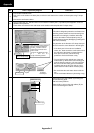
* If the drain port is frozen due to installation
status, etc., draw around the cord heater so that
the end part of the heater is inserted into the
drain port. In this case, add some fixing
positions to fix the cord heater surely.
* The end part from the marked part of the cord
heater heats up. When there is the heating part
near the electric parts box, a fire may generate.
Be sure to set the heating part on the outdoor
unit base plate at the fan room side or near it.
(within 20cm from the outdoor unit base plate)
* Be careful that the cord heater does not hit the
fan.
Fix the cord heater without any loosening or sag.
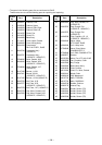
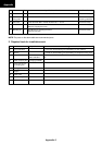
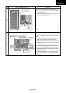
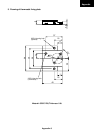
2-3
Drill a hole on the side cabinet (R) for fixing the
thermostat fixing plate.
Ø5 hole at two positions
When drilling a hole on the side cabinet (R), be
sure not to damage the cabinet.
A
dded
h
o
l
e
2
-
φ
5
Side cabinet
(
R
)
7
5
46
Ø9.1 P-shape clamp
PV
C
tub
e
The PV
C
tube must be inserted
into th
e
c
or
d
h
ea
t
e
r
be
tw
ee
n
the fixin
g
screws in order to
protect the cord heater from
th
ese
sc
r
e
w
s
.
U
n
de
r no
ci
r
cu
m
s
t
a
n
ces
m
us
t
th
e
t
ube
be
a
llow
ed
to ri
de
ov
e
r
the tip of the fixing screws.
Enlar
g
e
d
marked par
t
Heatin
g
par
t