


– 39 –
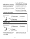
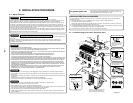
9-3-3. Evacuating
After the piping has been connected to all indoor unit(s),
you can perform the air purge together at once.
AIR PURGE
Evacuate the air in the connecting pipes and in the
indoor unit using vacuum pump. Do not use the
refrigerant in the outdoor unit. For details, see the
manual of vacuum pump.
Use a vacuum pump
Be sure to use a vacuum pump with counter-flow
prevention function so that inside oil of the pump does not
flow backward into pipes of the air conditioner when the
pump stops. (If inside oil of the vacuum pump enters into
the air conditioner which adopts R410A, a trouble of the
refrigeration cycle may be caused.)
1. Connect the charge hose from the manifold valve to the
service port of the gas side packed valve.
2. Connect the charge hose to the port of vacuum pump.
3. Open fully the low pressure side handle of the gauge
manifold valve.
4. Operate the vacuum pump to start for evacuating.
Perform evacuating for about 15 minutes if the piping
length is 20 meters. (15 minutes for 20 meters)
(assuming a pump capacity of 27 liters per minute.)
Then confirm that the compound pressure gauge
reading is –101 kPa ( –76 cmHg).
5. Close the low pressure side
valve handle of gauge manifold.
6. Open fully the valve stem of
the packed valves (both side
of Gas and Liquid).
7. Remove the charging hose
from the service port.
8. Securely tighten the caps
on the packed valves.
Fig. 9-3-5
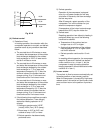
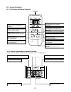
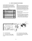
9-3. Outdoor Unit
9-3-1. Installation Place
• A place which provides the spaces around the
outdoor unit as shown in the left diagram.
• A place which can bear the weight of the
outdoor unit and does not allow an increase in
noise level and vibration.
• A place where the operation noise and
discharged air do not disturb your neighbors.
• A place which is not exposed to a strong wind.
• A place free of a leakage of combustible gases.
• A place which does not block a passage.
• When the outdoor unit is to be installed in an
elevated position, be sure to secure its feet.
•
An allowable length of the connecting pipe is up 15m.
• An allowable height level is up to 10 m.
• A place where the drain water does not raise
any problem.
CAUTION
1. Install the outdoor unit without anything
blocking the air discharging.
2. When the outdoor unit is installed in a place
exposed always to a strong wind like a coast or
on a high story of a building, secure the normal
fan operation using a duct or a wind shield.
3. Specially in windy area, install the unit to
prevent the admission of wind.
4. Installation in the following places may result
trouble. Do not install the unit such places.
• A place full of machine oil.
• A saline-place such as coast.
• A place full of sulfide gas.
• A place where high-frequency waves are
likely to be generated
as from audio
equipment,
welders, and
medical
equipment.
Strong
wind
90˚
Obliquity Roughness Warp
Fig. 9-3-1
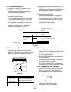
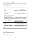
9-3-2. Refrigerant Piping Connection
Flaring 1. Cut the pipe with a pipe cutter.
Outer dia. of
copper pipe
6,35
9,52
12,7
Conventional
tool used
1,0 to 1,5
1,0 to 1,5
1,0 to 1,5
R410A
tool used
0 to 0,5
0 to 0,5
0 to 0,5
Die Pipe
A
Outer dia. of
copper pipe
6,35
9,52
12,7
R410A
1,5 to 2,0
1,5 to 2,0
2,0 to 2,5
Fig. 9-3-2
2. Insert a flare nut into the pipe, and flare the pipe.
• Projection margin in flaring : A (Unit : mm)
Rigid (Clutch type)
Imperial (Wing nut type)
Fig. 9-3-3
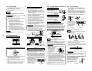
Tightening Connection
Align the centers of the connecting pipes and tighten the
flare nut as far as possible with your fingers Then
tighten the nut with a spanner and torque wrench as
shown in the figure.
CAUTION
• Do not apply excess torque. Otherwise, the nut
may crack depending on the conditions.
(Unit : N·m)
Outer dia. of copper pipe
ø6,35 mm
ø9,52 mm
ø12,7 mm
Tightening torque
14 to 18 (1,4 to 1,8 kgf•m)
33 to 42 (3,3 to 4,2 kgf•m)
50 to 62 (5,0 to 6,2 kgf•m)
• Tightening torque of flare pipe connections
Pressure of R410A becomes higher than that of R22.
(Approx. 1,6 times) Therefore, using a torque wrench,
tighten firmly the flare pipe connecting sections which
connect the indoor and outdoor units
up to the specified tightening torque.
Incorrect connections may cause not
only a gas leakage, but also a trouble
of the refrigeration cycle.
Flare at
indoor
unit side
Flare at
outdoor
unit side
Compound
pressure
gauge
Pressure gauge
Manifold valve
Handle Hi
(Keep full closed)
Charge hose
(For R410A only)
Vacuum pump
adapter for
counter-flow
prevention
(For R410A only)
Packed valve at liquid side
Packed valve at gas side
Service port
(Valve core (Setting pin))
Connecting
pipe
Handle Lo
Charge hose
(For R410A only)
-101kPa
(-76cmHg)
Vacuum
pump
Half union
Flare nut
Externally
threaded side
Internally
threaded side
Use a wrench
to secure.
Use a torque wrench
to secure.
Fig. 9-3-4
CAUTION
•
KEEP IMPORTANT 4 POINTS FOR PIPING WORK
1. Take away dust and moisture
(Inside of the connecting pipes.)
2. Tight connection (between pipes and unit)
3. Evacuate the air in the connecting pipes using
VACUUM PUMP.
4. Check gas leak (connected points)
Packed Valve Handling Precautions
• Open the valve stem all the way out; but do not try
to open it beyond the stopper.
• Securely tighten the valve stem cap with torque in
the following table :
5m
m
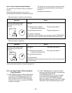
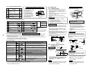
9-3-4. Wiring Connection
1. Remove the electric parts cover from the outdoor
unit.
2. Connect the connecting cable to the terminal as
identified with their respective matched numbers
on the terminal block of indoor and outdoor unit.
3. When connecting the connecting cable to the
outdoor unit terminal, make a loop as shown
installation diagram of indoor and outdoor unit, to
prevent water coming in the outdoor unit.
4. Insulate the unused cords (conductors) with water
coming in the outdoor unit. Process them so that
they do not touch any electrical or metal parts.
Stripping length of connecting cable
Terminal block (Connecting cable)
Connecting
cable
Connecting cable
Power
cord
Power
cord
Earth line
10
10
LN
30
10
30
40
10
40
123
Model
Power source
Maximum running current
Plug socket & fuse rating
Power cord
RAS-10YKV-E/RAS-13YKV-E
50/60 Hz, 220 – 240 V Single phase
8,5A
10A
H07RN-F or 245IEC66 (2,0mm² or more)
Hexagonal
wrench is
required.
Gas side
(ø12,7 mm)
Gas side
(ø9,52 mm)
Liquid side
(ø6,35 mm)
Service port
50 to 62 N•m
(5,0 to 6,2 kgf•m)
33 to 42 N•m
(3,3 to 4,2 kgf•m)
14 to 18 N•m
(1,4 to 1,8 kgf•m)
14 to 18 N•m
(1,4 to 1,8 kgf•m)
CAUTION
• Wrong wiring connection may cause some
electrical parts burn out.
• Be sure to comply with local codes on running
the wire from outdoor unit to indoor unit (size of
wire and wiring method etc.)
• Every wire must be connected firmly.
NOTE : Connecting cable
• Wire type : More than H07RN-F or 245IEC66
(2,0mm² or more)
Fig. 9-3-7
Fig. 9-3-8
9-3-5. Gas Leak Test
• Flare nut connections
(Outdoor unit)
• Valve stem cap connection
• Service port cap connection
Flare nut connections
(Indoor unit)
TEMPORARY
TEMPORARY
button
Fig. 9-3-9
• Check the flare nut connections, valve
stem cap connections and service port cap
connections for gas leak with a leak
detector or soap water.
9-3-6. Test Operation
To switch the TEST RUN (COOL) mode,
press TEMPORARY button for 10 sec.
(The beeper will make a short beep.)
Fig. 9-3-10
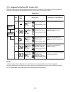
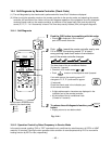
9-3-7. Auto Restart Setting
This product is designed so that, after a
power failure, it can restart automatically in
the same operating mode as before the
power failure,
Information
The product was shipped with Auto
Restart function in the off position.
Turn it on as required.
How to Set the Auto Restart
• Press and hold down the TEMPORARY
button for about 3 seconds. After 3
seconds, the electronic beeper makes
three short beeps to tell you the Auto
Restart has been selected.
• To cancel the Auto Restart, follow the
steps described in the section Auto Restart
Function of the Owner’s Manual.
Fig. 9-3-6