


– 16 –
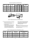
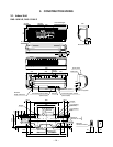
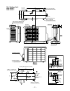
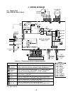
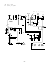
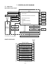
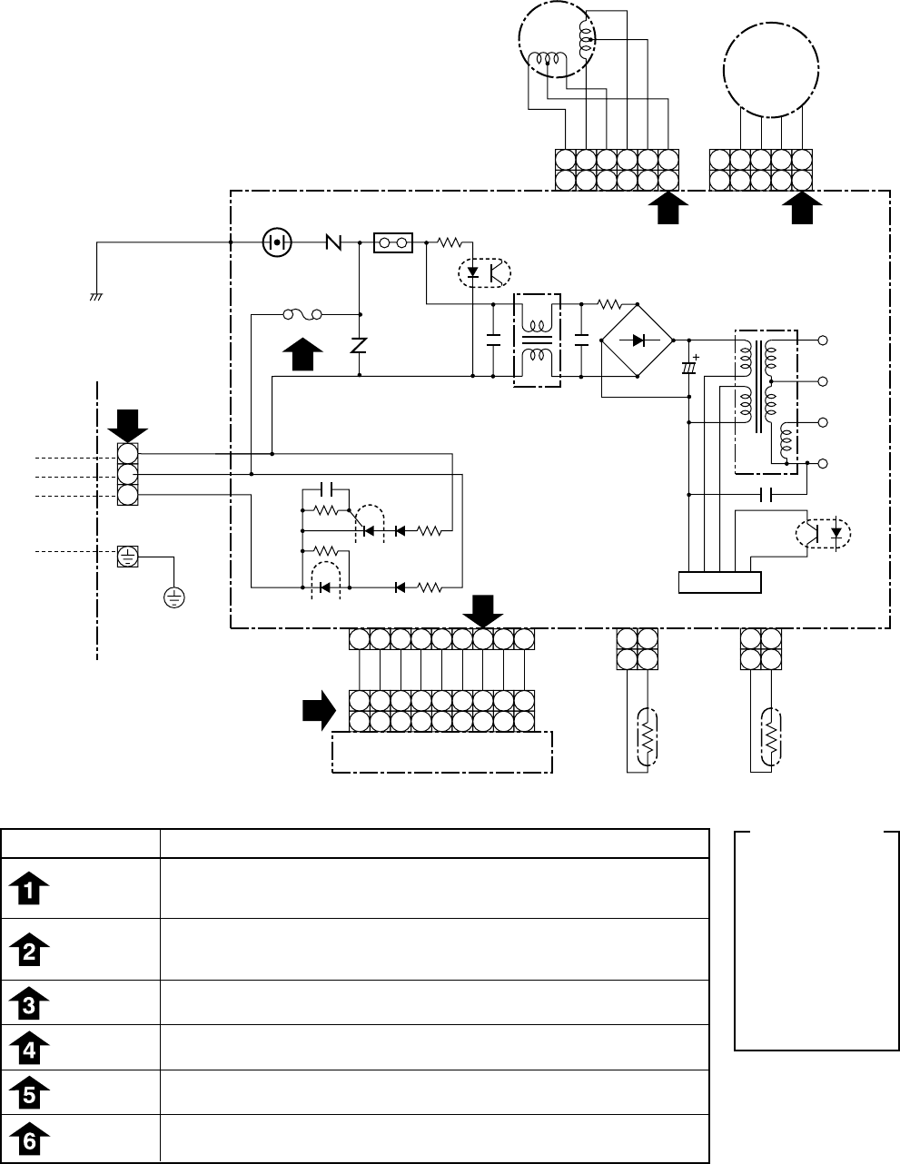
4. WIRING DIAGRAM
4-1. Indoor Unit
RAS-10YKV-E, RAS-13YKV-E
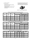
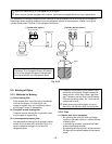
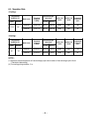
Table 4-1-1 Simple check points for diagnosing faults
Check items
OPERATION
indicator
Terminal
block
Fuse
6,3A
DC 5V
DC 12V
DC 35V
Diagnosis result
Check to see if the OPERATION indicator goes on and off when the main
switch or breaker is turned on, or the power cord is plugged in the wall
outlet. (Check the primary and secondary voltage of transformer.)
Check for power supply voltage between
Q
–
R
. (Refer to the name
plate.) (Check the primary and secondary voltage of transformer.)
Check for fluctuate voltage between
R
–
S
. (DC 15 to 60V)
Check to determine if the fuse is open.
(Check Varistor : R109, R21)
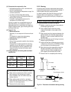
Check for voltage at the pink lead of the infrared rays receive parts.
(Check the transformer and the rated voltage power supply circuit.)
Check for voltage at the
QS
lead of louver motor.
(Check the transformer and the rated voltage power supply circuit.)
Check for voltage at the CN10 connector side point.
(Check the transformer and the rated voltage power supply circuit.)
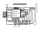
MAIN P.C. BOARD
(MCC-772)
BLK
P04
CN30
CN23
INDOOR
TERMINAL
BLOCK
INDOOR
UNIT
OUTDOOR
UNIT
CN07
CN10
TO1
DC35V
DC12V
DC7V
DC0V
C06
C02
IC04
R116
C15
R21
J04
F01 FUSE
T6,3A 250V
R109
VARISTOR
SG01 DSA
L01
C01
R01
DB01
HEAT
EXCHANGER
SENSOR
(TC)
IC
IC01
CN01
IC02
21
21
BLK
BLK
THERMO
SENSOR
(TA)
CN03
CN13
CN25
INFRARED RAYS RECEIVE
AND INDICATION PARTS
21
21
BLK
1
1
2
3
BLK
WHI
GRN & YEL
RED
1
1
BLU
BLK
2
2
2
BLU
3
3
3
BLU
4
4
4
BLU
5
5
5
BLU
6
6
6
BLU
7
7
7
PNK
8
8
8
BLK
9
9
9
WHI
6 5 4 3 2 1
6 5 4 3 2 1
4 3 2
FAN MOTOR
LOUVER
MOTOR
4
5
5
3 2
1
1
BLU
PNK
YEL
ORN
RED
BRW
DC MOTOR
2
4
1
3
65
BROWNBRW :
COLOR
IDENTIFICATION
REDRED :
WHITEWHI :
YELLOWYEL :
BLUEBLU :
BLACKBLK :
GRAYGRY :
PINKPNK :
ORANGEORN :
GREEN &
YELLOW
GRN
&YEL
:
For detailed diagnostic procedure, refer to the service data.
DSA : Surge Absorber