


TIC-LF470B
4
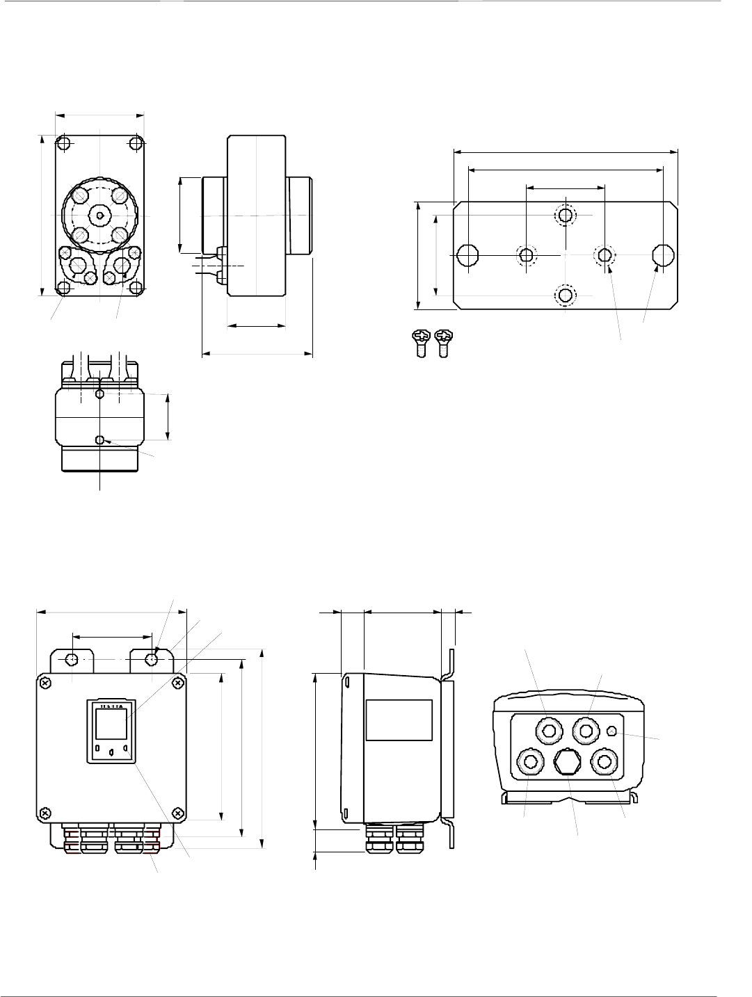
Installation
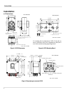
Dimensions
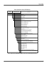
If a mounting plate is needed for the LF470, fix the plate (a)
above to the bottom of the LF470. Depending on which pair of
screw holes used, the mounting angle changes by 90°.
2.20(56)
1.46(37)
2
.76(70)
This length becomes 78mm if the pipe
connection port thread is Rc(PT)1/2
and Rc(PT)3/4.
Signal cable
φ0.28(φ7)
Excitation cable
φ
0.28(φ7)
2-M4
(Mou nt in g scr ew holes)
4.02(102)
1.18(30)
φ1.93(φ49)
*
*
Figure3. LF470 Dimensions
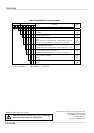
1.18(30)
2.95(75)
3
.39(86)
**
**
* *
2-φ0.24(φ6) hole
4-φ0.20(φ5) hole
Detector mounting plate
(4mm thick)
Mounting screws
1.18(30)
1.57(40)
Figure4. LF470 Mounting Board
矢視 A
信号ケーブル
グランド
電源ケーブルグランド
封止栓
励磁ケーブルグランド
電流出力ケーブルグランド
接地端子
(M4)
取付金具
4-
φ
11
取付金具
82
(36) 156
13
151
178
200
151
74 ±0.3
25
LCD 表示器
赤外線スイッチ
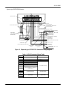
Excitation cable ground
5.94
(
151
)
5.94(151)
2.91(74)
4
–
0.43( 11)
Attachmen
t
LCD display
7.01
(
178
)
7.87(
2
00)
IR Switc h
Cable ground
6.14
(
156
)
1.42(36)
0.98(25) 3.23(82)
0.51
(
13
)
I/O cable groun
d
Ground termina
l
(M4)
Power supply cable ground
Blind screw
Signal cable groun
d
Figure 5. Separate type converter LF612
Unit : inch (mm)
Unit : inch (mm)
N
ote: 1 inch = 25.4mm
N
ote: 1 inch = 25.4m
m
Unit : inch (mm)
N
ote: 1 inch = 25.4m
m