


TIC-LF470B
3
Communications output :
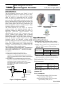
• HART (std.) — Digital signal is superimposed on
4–20mAdc current signal as follows:
Conforms to HART protocol
Load resistance: 240 to 750Ω
Load capacitance: 0.25µF maximum
Load inductance: 4mH maximum
• PROFIBUS(opt.)
Protocol: PROFIBUS-PA
Baud rate: 31.25kbps
Bus voltage: 9-30VDC
Consumption electric current of bus: less than 16mA
Manufacture Ident-No.: 093B
HEX
Standard Ident-No.: 9740
HEX
Slave address: 0-126 (Default address is 126)
Profile: Profile Ver.3.01 for Process Control
Devices
Function blocks: AI(Flow)×1 , Totalizer×1
LCD display:
Full dot-matrix 128×128 dot LCD display
(back–light provided)
The data on the LCD inside the converter can rotate
to 90, 180, and 270 degrees by a software, without
rotating the indicator itself. (Combined type only)
Parameter settings — Parameters can be set as
follows:
• IR Switches: Three key switches are provided to
set configuration parameters.
• Digital communication: The AF900 hand-held
terminal or PROFIBUS is needed to set
parameters.
• Zero adjustment: Zero point adjustment can be
started by pressing the switch in the converter.
• Damping: 0.5 to 60 seconds (selectable in one
second increments)
“Field re-verification”
Mag-Prover – Toshiba’s
Zero span calibration tool allows unit to be
re-calibrated and verified using an internal software
program. (For more information contact Toshiba
International Corp.)
Conditions when power fails:
Parameter setting values are stored in non–volatile
memory and the values will be restored when the
power returns to normal condition. The outputs and
display will remain as follows when power fails.
• Current output: 0mAdc
• Digital output: OFF
• LCD display: No display
• PROFIBUS: No communication
Power supply:
One of the following can be selected:
• 100 to 240Vac, 50/60Hz (std.)
(allowable voltage 80 to 264Vac)
• 24Vdc (allowable voltage 18 to 36Vdc)
• 110Vdc (allowable voltage 90 to 130Vdc)
Surge protection:
Arresters are installed in the power supply and a
current signal output circuit to help protect the meter
from lightning and improve personnel safety.
Case: Aluminum alloy (equal to IP 67)
Coating: Acrylic resin-baked coating, pearl–gray
colored
Cable connection port:
Cable glands —
Provided as standard, OD of 11 to 13mm
Material Nylon 66
G (PF) 1/2 male screws
Applicable diameter —
0.433 to 0.512 inch (11 to 13mm)
Note: When PROFIBUS option is specified, cable gland size is φ
6~8mm for signal cable, φ11~13mm for power cable
Vibration resistance:
No resonance to the following levels of vibration:
• 10 to 150Hz with acceleration of 9.8m/s
2
• Vibration of 30Hz with 29.4 m/s
2
in 4h in each
direction will not cause any defect to unit.
Note: Avoid using the flowmeter in an environment with
constant vibration.
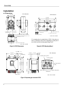
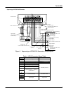
Dimensions :
See Figure 5
MTBF:
Converter: 220,000 hours (25 years) at 77 °F (25 °C)
based on strict military specification
MIL-HDBK-217F
Detector: 350,000 hours (40 years) at 77 °F (25 °C)
based on strict military specification
MIL-HDBK-217F