31
Toshiba
HWS-1102H-E, 1402H-E
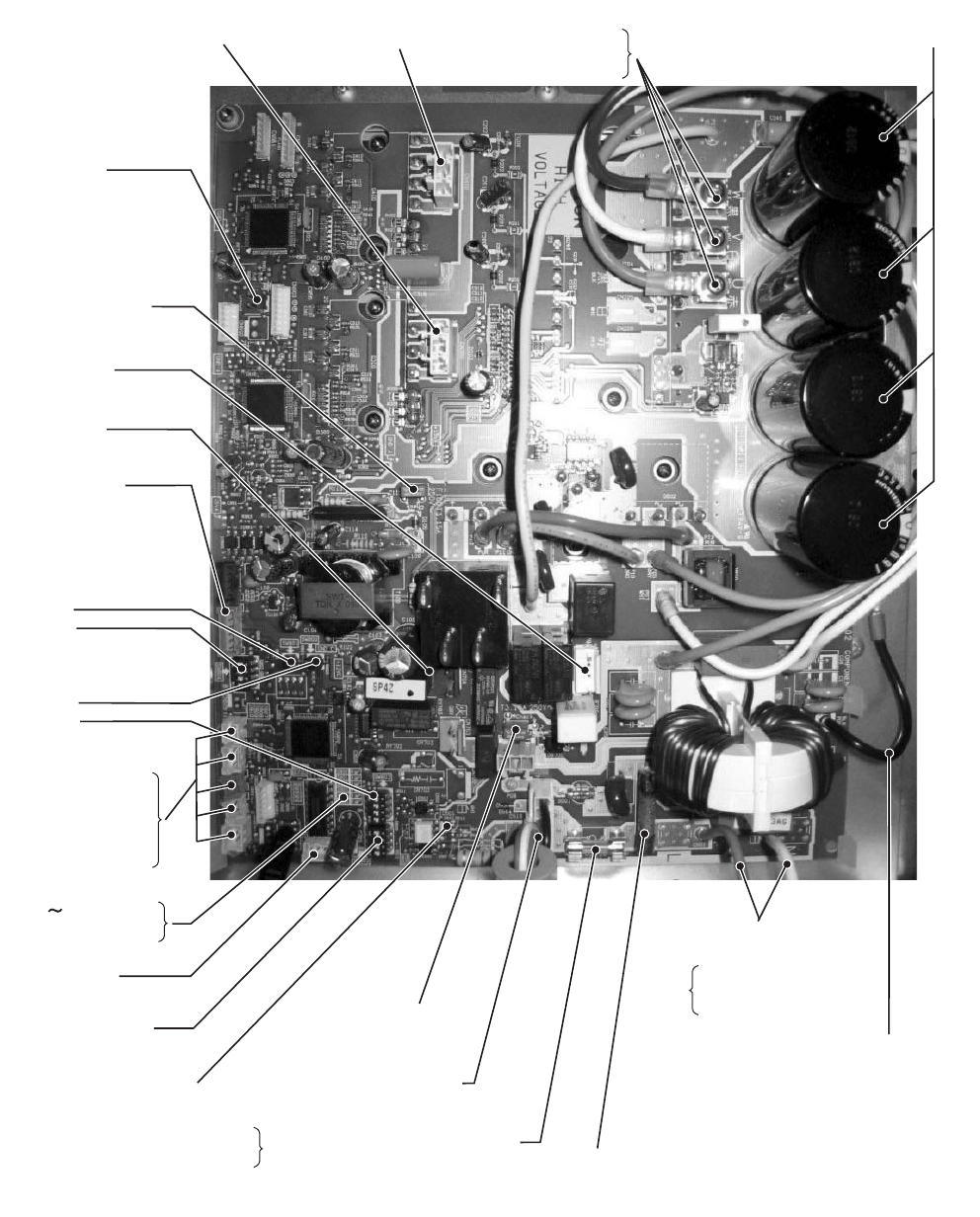
Fan motor output (Upper)
CN400(White)
Fan motor output (Lower)
CN300(White)
Case thermostat connector
CN609(Blue)
Power circuit protection
fuse
F100(250V,3.15A,
plastic case)
4-way valve connector
CN701(White)
Compressor ON output
connector
CN704(Blue)
External input connector
CN610(Yellow)
Special operation switches
SW801
SW804
Display change-over
switches
SW800
SW803
PMV connector
CN710(White)
Initialization switch
SW802
4-way valve protection fuse
F700(250V,3.15A
plastic case)
Power supply protection fuses
F01
(250V,25A)
Earth lead wire
P09(Black)
Connecting cable connector
CN04(White)
Connecting cable protection fuse
F03(250V,10A)
Electrolytic capacitors
Compressor output terminals
CN202
CN201
CN200
Power supply connection
lead wires
P01(Red)
P02(White)
P03(Black)
Temperature sensor
connectors
TL CN604(White)
TD CN603(White)
TO CN602(Yellow)
TE CN601(White)
TS CN600(White)
Alive, abnormal display LEDs
D800 804(Yellow)
D805(Green)
Hydro-outdoor communication
signal LEDs
D503 (Green, Outdoor =>Hydro)
D502 (Amber, Hydro => Outdoor)
+00A09-002_01EN_SVM_ALL_Air_to_Water.book Page 31 Monday, October 5, 2009 2:09 PM


