


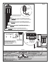

Station Decoder Installation
The station decoder module is available in 1-station, 2-station or 4-station configuration. The decoder modules are installed into
the TDC output board terminals.
The stand-alone TDC model can handle up to 100 stations per output board. These stations can be connected to the output
board terminals in any configuration (25 stations connected to each of the four terminal pairs or 100 stations connected to one
terminal pair, etc.). The decoder modules can be connected in parallel anywhere on the two-wire communication line connected
to the station terminals. Each station can activate up to two solenoids.
It is recommended that the decoder modules are installed in an approved valve box to provide easy access to the wiring. Use
high-voltage waterproofing to all the wire connections.
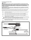
Recommended Controller-to-Decoder cable: 14 AWG (2.5mm
2
), solid copper, jacketed 2-conductor, direct burial. The
preferred wire make and model is the Paige Irrigation Wire, Spec P7350D.
Recommended Decoder-to-Solenoid cable: 14 AWG (2.5mm
2
), solid copper, 2-conductor, direct burial. The preferred wire
make and model is the Paige Irrigation Wire, Spec P7351D.
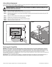
IMPORTANT!
Cable Splices: In order for the wire connections to comply with the 2005 edition of the National Electric Code®
Article 300.5 (Underground Installations) and 110.14 (Electrical Connections), in wet or damp locations, the connector
must be listed under specification “UL 486D” if installed in a valve box. It must be listed under specification “UL 486D-
Direct Burial” if buried in dirt. This requirement applies to all electrical connections in wet or damp locations,
regardless of voltage. The 3M DBY-6 and DBR-6 are listed as “UL 486D-Direct Burial” and meet these requirements for
all underground installations.
Cable Burial Depth: The TDC decoder operate at voltages between 30–40 volts. The 2005 edition of the National
Electrical Code®, Article 300-5, requires that wires and cables subjected to voltages higher than 30 volts are to have a
minimum cover of 24" (60.96 cm).
• Use only wire approved for direct burial if installing the wires underground without conduit.
• All field wiring splices must be accessible to facilitate troubleshooting and/or service.
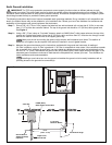
Step 1 – Route communication cable from the controller to the station decoder module installation location.
The maximum wire length between the controller and the decoder module is 15,000' (4500m).
Step 2 – Secure the communication wires to terminal 1 of the TDC output board. White wire onto the 1st terminal and black
wire onto the second terminal. See Figure 4.
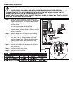
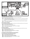
Step 3 – Install the decoder module in a valve box. Record the decoder module’s address number found on the side label.
This address number identifies the station(s) that the decoder module control.
Step 4 – Secure the communication wires to the decoder module’s black and white wires. Connect the black communication
wire to the black decoder module wire. Connect the remaining communication wire (red or white) to the white
decoder module wire. Use proper water proofing method for all wire connections.
Step 5 – Route output wires from the decoder module to the solenoid.
The maximum wire length between the decoder module and the solenoid is 410' (125m).
Step 6 – Connect the solenoid wires to the decoder module’s station wires. The station wires are color coded for easy
identification. Connect the solid colored (red, green, orange or blue) station wire to the red/white solenoid wire.
Connect the similar color station wire with black stripe to the black solenoid wire. Waterproof all wire connections.
Step 7 – Connect an additional solenoid to the station wire as necessary.
Each station has a maximum load of two solenoids.
Step 8 – Repeat Steps 3–8 for additional decoder modules.